Arduino Uno R3 with MQ Gas Sensors and I2C LCD Display
Circuit Documentation
Summary of the Circuit
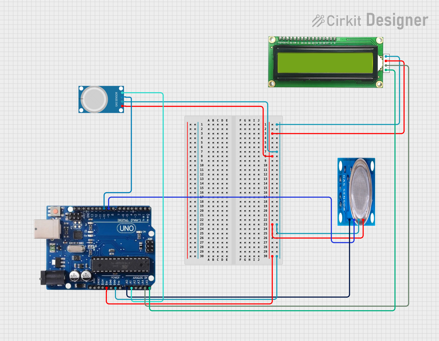
The circuit in question appears to be a gas detection and monitoring system utilizing two gas sensors (MQ-5 and MQ-4), an Arduino Uno R3 as the central processing unit, and an MKE-M07 LCD1602 I2C module for displaying sensor readings. The MQ-5 sensor is capable of detecting various gases such as LPG, natural gas, and coal gas, while the MQ-4 sensor is specialized for detecting methane. The Arduino Uno R3 reads the analog and digital outputs from these sensors and likely processes the data to display the gas concentrations on the LCD module.
Component List
MQ-5 Gas Sensor
- Pins: VCC, GND, Digi Out, Analog out
- Description: A gas sensor designed for detecting LPG, natural gas, and coal gas.
MQ-4 Gas Sensor
- Pins: A0, D0, GND, VCC
- Description: A gas sensor designed for detecting methane.
Arduino Uno R3
- Pins: USB Port, Power Jack, Not Connected, IOREF, RESET, 3.3V, 5V, GND, VIN, A0 to A5, SCL, SDA, AREF, Digital Pins 0 to 13
- Description: A microcontroller board based on the ATmega328P, widely used for building digital devices and interactive objects.
MKE-M07 LCD1602 I2C
- Pins: GND, 5V, SDA, SCL
- Description: An alphanumeric LCD display module with an I2C interface for displaying text and numbers.
Wiring Details
MQ-5 Gas Sensor
- VCC: Connected to the 5V supply from the Arduino Uno R3.
- GND: Connected to the ground (GND) on the Arduino Uno R3.
- Digi Out: Connected to digital pin 9 on the Arduino Uno R3.
- Analog out: Connected to analog pin A0 on the Arduino Uno R3.
MQ-4 Gas Sensor
- VCC: Connected to the 5V supply from the Arduino Uno R3.
- GND: Connected to the ground (GND) on the Arduino Uno R3.
- A0: Connected to analog pin A1 on the Arduino Uno R3.
- D0: Connected to digital pin 10 on the Arduino Uno R3.
Arduino Uno R3
- 5V: Provides power to both MQ-5 and MQ-4 gas sensors, and the MKE-M07 LCD1602 I2C module.
- GND: Common ground for the entire circuit.
- A0: Receives the analog output from the MQ-5 sensor.
- A1: Receives the analog output from the MQ-4 sensor.
- Digital Pin 9: Receives the digital output from the MQ-5 sensor.
- Digital Pin 10: Receives the digital output from the MQ-4 sensor.
- A4/SDA: Connected to the SDA pin of the MKE-M07 LCD1602 I2C module.
- A5/SCL: Connected to the SCL pin of the MKE-M07 LCD1602 I2C module.
MKE-M07 LCD1602 I2C
- GND: Connected to the ground (GND) on the Arduino Uno R3.
- 5V: Powered by the 5V supply from the Arduino Uno R3.
- SDA: Connected to the SDA pin (A4) on the Arduino Uno R3.
- SCL: Connected to the SCL pin (A5) on the Arduino Uno R3.
Documented Code
No code has been provided for the microcontroller. The expected code should initialize the sensors, read their outputs, process the data, and display the results on the LCD module. It should also include setup and loop functions, sensor calibration routines, and I2C communication setup for the LCD display.