
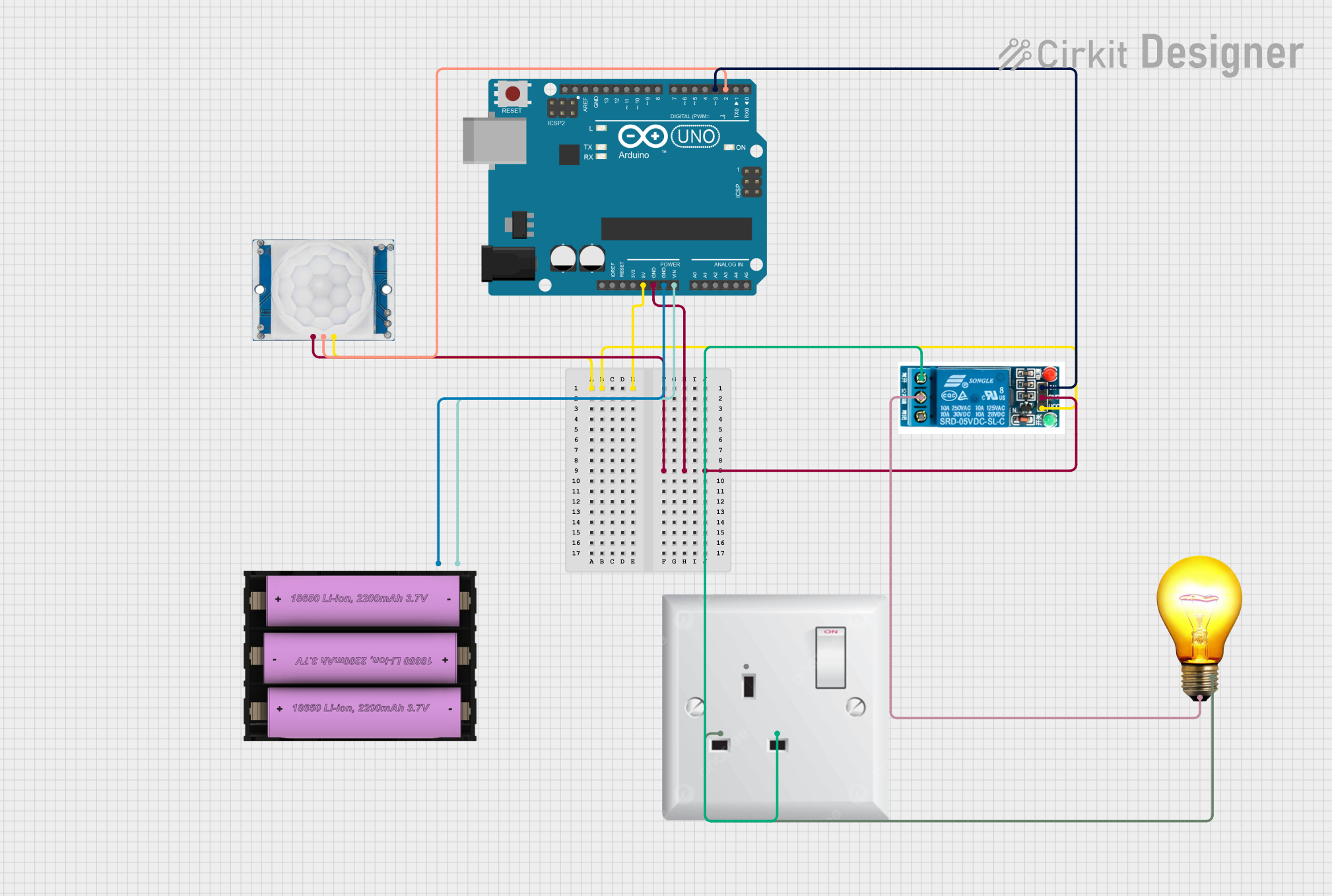
Circuit Documentation
Summary
This circuit is designed to control an AC bulb using a 5V relay and an HC-SR501 PIR motion sensor, all managed by an Arduino UNO. The PIR sensor detects motion and signals the Arduino, which then activates the relay to turn on the AC bulb. The circuit is powered by a 7V battery.
Component List
Arduino UNO
- Description: A microcontroller board based on the ATmega328P.
- Pins: UNUSED, IOREF, Reset, 3.3V, 5V, GND, Vin, A0, A1, A2, A3, A4, A5, SCL, SDA, AREF, D13, D12, D11, D10, D9, D8, D7, D6, D5, D4, D3, D2, D1, D0
5V Relay
- Description: An electromechanical switch used to control high voltage devices.
- Pins: Normally Open, Common terminal, Normally Closed, In, GND, VCC
HC-SR501 PIR Motion Sensor
- Description: A sensor that detects motion by measuring changes in infrared radiation.
- Pins: Output, Ground, Power Supply
Set Battery (7V)
- Description: A 7V battery used to power the circuit.
- Pins: +, -
AC Bulb
- Description: An AC-powered light bulb.
- Pins: P, N
AC Wall Plug Point
- Description: A standard AC wall plug point.
- Pins: E, N, L
Wiring Details
Arduino UNO
- 5V: Connected to VCC of the 5V relay and Power Supply of the HC-SR501 PIR motion sensor.
- GND: Connected to GND of the 5V relay, Ground of the HC-SR501 PIR motion sensor, and - of the 7V battery.
- Vin: Connected to + of the 7V battery.
- D3: Connected to In of the 5V relay.
- D2: Connected to Output of the HC-SR501 PIR motion sensor.
5V Relay
- VCC: Connected to 5V of the Arduino UNO.
- GND: Connected to GND of the Arduino UNO.
- In: Connected to D3 of the Arduino UNO.
- Normally Open: Connected to L of the AC wall plug point.
- Common terminal: Connected to P of the AC bulb.
HC-SR501 PIR Motion Sensor
- Power Supply: Connected to 5V of the Arduino UNO.
- Ground: Connected to GND of the Arduino UNO.
- Output: Connected to D2 of the Arduino UNO.
Set Battery (7V)
- +: Connected to Vin of the Arduino UNO.
- -: Connected to GND of the Arduino UNO.
AC Bulb
- P: Connected to Common terminal of the 5V relay.
- N: Connected to N of the AC wall plug point.
AC Wall Plug Point
- L: Connected to Normally Open of the 5V relay.
- N: Connected to N of the AC bulb.
Documented Code
#define SENSOR_PIN 2
#define RELAY_PIN 3

void setup()
{
  pinMode(RELAY_PIN, OUTPUT);
  pinMode(SENSOR_PIN, INPUT);
  //Serial.begin(9600);
}

void loop()
{
  //If object movement is detected then the sensor value will be 1 else the value will be 0
  int sensorValue = digitalRead(SENSOR_PIN);
  //Serial.println(sensorValue);
  if (sensorValue == HIGH)
  {
    digitalWrite(RELAY_PIN, LOW);  //Relay is low level triggered relay so we need to write LOW to switch on the light
  }
  else
  {
    digitalWrite(RELAY_PIN, HIGH);
  }
}
This code initializes the PIR sensor and the relay. When motion is detected by the PIR sensor, the relay is activated to turn on the AC bulb. The relay is low-level triggered, so writing LOW to the relay pin turns on the light, and writing HIGH turns it off.