Cirkit Designer
Your all-in-one circuit design IDE
Home /
Project Documentation
Arduino UNO-Based Smart Light System with I2C LCD and BH1750 Light Sensor
Circuit Documentation
Summary
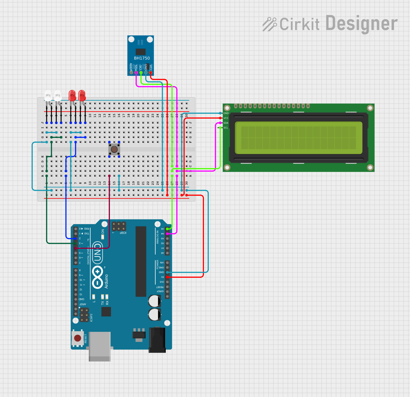
This circuit involves an Arduino UNO microcontroller interfacing with various components including pushbuttons, LEDs, an I2C LCD, and a BH1750 light sensor. The circuit is designed to demonstrate basic input and output operations, as well as I2C communication.
Component List
Pushbutton
- Description: A simple pushbutton used for user input.
- Pins: Pin 1 (in), Pin 2 (in), Pin 3 (out), Pin 4 (out)
Arduino UNO
- Description: A microcontroller board based on the ATmega328P.
- Pins: UNUSED, IOREF, Reset, 3.3V, 5V, GND, Vin, A0, A1, A2, A3, A4, A5, SCL, SDA, AREF, D13, D12, D11, D10, D9, D8, D7, D6, D5, D4, D3, D2, D1, D0
16x2 I2C LCD
- Description: A 16x2 character LCD display with I2C interface.
- Pins: GND, VCC, SDA, SCL
BH1750
- Description: A digital light sensor with I2C interface.
- Pins: VCC, GND, SCL, SDA, ADDR
LED: Two Pin (red)
- Description: A red LED with two pins.
- Pins: cathode, anode
LED: Two Pin (white)
- Description: A white LED with two pins.
- Pins: cathode, anode
Wiring Details
Pushbutton
- Pin 2 (in) connected to Arduino UNO D4
- Pin 4 (out) connected to GND
Arduino UNO
- D2 connected to anode of both red LEDs
- D3 connected to anode of both white LEDs
- D4 connected to Pin 2 (in) of Pushbutton
- A4 connected to SDA of BH1750 and 16x2 I2C LCD
- A5 connected to SCL of BH1750 and 16x2 I2C LCD
- 5V connected to VCC of BH1750 and 16x2 I2C LCD
- GND connected to cathode of both white LEDs, cathode of both red LEDs, Pin 4 (out) of Pushbutton, GND of BH1750, and GND of 16x2 I2C LCD
16x2 I2C LCD
- GND connected to GND
- VCC connected to 5V
- SDA connected to A4
- SCL connected to A5
BH1750
- VCC connected to 5V
- GND connected to GND
- SDA connected to A4
- SCL connected to A5
LED: Two Pin (red)
- anode connected to D2
- cathode connected to GND
LED: Two Pin (white)
- anode connected to D3
- cathode connected to GND
Documented Code
Arduino UNO Code (sketch.ino)
void setup() {
  // put your setup code here, to run once:

}

void loop() {
  // put your main code here, to run repeatedly:

}
Additional Documentation (documentation.txt)
This documentation provides a comprehensive overview of the circuit, including a summary, detailed component list, wiring details, and the code used in the microcontroller.