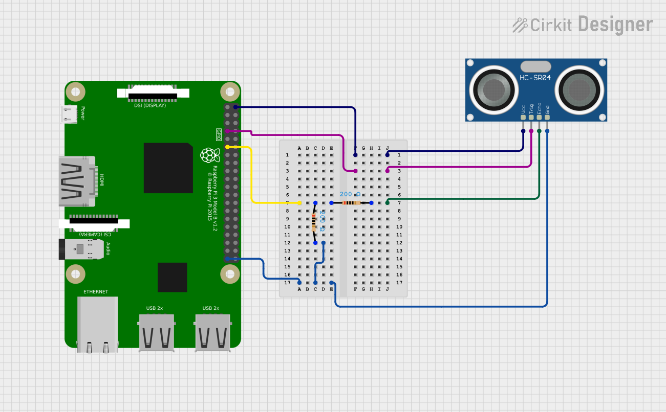
Raspberry Pi 3B-Based Ultrasonic Distance Measurement System

Circuit Documentation
Summary of the Circuit
This circuit integrates a Raspberry Pi 3B with an HC-SR04 Ultrasonic Sensor and uses two resistors to form a voltage divider. The Raspberry Pi 3B is responsible for controlling the sensor and processing the data it receives. The HC-SR04 sensor is used to measure distances by emitting ultrasonic waves and detecting the reflected signal. The resistors are used to interface the ECHO pin of the HC-SR04 with the Raspberry Pi, likely to step down the voltage to a safe level for the GPIO pin.
Component List
Raspberry Pi 3B
- Description: A single-board computer with GPIO pins for interfacing with various electronic components.
- Pins: 40 GPIO pins including power, ground, and various I/O pins.
- Purpose: Acts as the main controller for the circuit, providing power and control signals to the HC-SR04 sensor and processing its output.
HC-SR04 Ultrasonic Sensor
- Description: An ultrasonic distance sensor capable of measuring distances by emitting and receiving ultrasonic waves.
- Pins: VCC, TRIG, ECHO, GND.
- Purpose: To measure the distance to an object by emitting ultrasonic pulses and measuring the time taken for the echoes to return.
Resistor (200 Ohms)
- Description: A passive two-terminal electrical component that implements electrical resistance as a circuit element.
- Pins: pin1, pin2.
- Properties: Resistance value of 200 Ohms.
- Purpose: Used in pairs to create a voltage divider, which is likely used to step down the voltage from the ECHO pin of the HC-SR04 sensor to a safe level for the Raspberry Pi GPIO pin.
Wiring Details
Raspberry Pi 3B
- 5V Power: Connected to the VCC pin of the HC-SR04 Ultrasonic Sensor.
- GPIO 7 (Pin 7): Connected to the TRIG pin of the HC-SR04 Ultrasonic Sensor.
- GPIO 11 (Pin 11): Connected to pin1 of the first 200 Ohm Resistor.
- Ground (Pin 39): Connected to pin2 of the first 200 Ohm Resistor and the GND pin of the HC-SR04 Ultrasonic Sensor.
HC-SR04 Ultrasonic Sensor
- VCC: Powered by the 5V pin of the Raspberry Pi 3B.
- TRIG: Controlled by GPIO 7 of the Raspberry Pi 3B.
- ECHO: Connected to pin2 of the second 200 Ohm Resistor.
- GND: Connected to the ground of the Raspberry Pi 3B and pin2 of the first 200 Ohm Resistor.
Resistor (200 Ohms)
- First Resistor:
- pin1: Connected to GPIO 11 of the Raspberry Pi 3B.
- pin2: Connected to pin1 of the second 200 Ohm Resistor and the GND pin of the HC-SR04 Ultrasonic Sensor.
- Second Resistor:
- pin1: Connected to pin1 of the first 200 Ohm Resistor.
- pin2: Connected to the ECHO pin of the HC-SR04 Ultrasonic Sensor.
Documented Code
There is no code provided for the microcontrollers in the circuit. The Raspberry Pi 3B would typically be programmed in Python or another suitable language to control the HC-SR04 Ultrasonic Sensor and process the distance measurements. The code would initialize the GPIO pins, send trigger pulses, and measure the duration of the received echo pulses to calculate the distance to an object. However, without the actual code, we cannot provide further documentation on the software aspect of this circuit.