
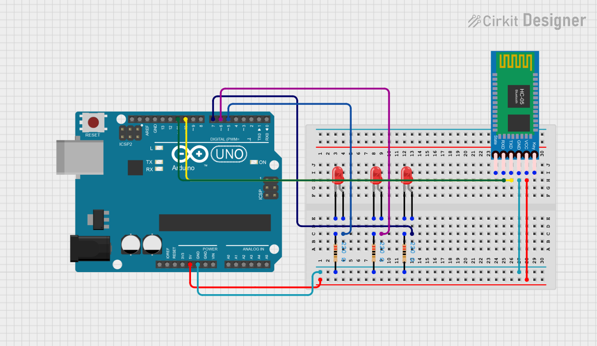
Circuit Documentation
Summary
This circuit is designed to control three red LEDs via an Arduino UNO microcontroller, which is also interfaced with an HC-05 Bluetooth module for wireless communication. The LEDs can be individually turned on and off through serial commands received by the Arduino, which are likely sent from a Bluetooth-connected device. The HC-05 module facilitates the Bluetooth communication, receiving data from a paired device and transmitting it to the Arduino for processing.
Component List
Arduino UNO
- Microcontroller board based on the ATmega328P
- It has 14 digital input/output pins, 6 analog inputs, a 16 MHz quartz crystal, a USB connection, a power jack, an ICSP header, and a reset button.
LED: Two Pin (red)
- A simple red light-emitting diode that emits red light when a forward current passes through it.
- It has an anode and a cathode pin for connecting to the power supply and ground, respectively.
Resistor
- A passive two-terminal electrical component that implements electrical resistance as a circuit element.
- In this circuit, resistors are used to limit the current flowing through the LEDs to prevent them from burning out.
HC-05 Bluetooth Module
- A wireless communication module that can be used to exchange data over short distances from fixed and mobile devices.
- It has pins for key, VCC, TXD, RXD, State, and GND.
Wiring Details
Arduino UNO
5Vpin is connected to the VCC pin of the HC-05 Bluetooth Module to provide power.GNDpin is connected to the ground pins of all the resistors and the GND pin of the HC-05 Bluetooth Module to provide a common ground.- Digital pins
D5,D6, andD7are connected to the anodes of the three red LEDs, respectively. - Digital pins
D10andD11are connected to the TXD and RXD pins of the HC-05 Bluetooth Module, respectively, to facilitate serial communication.
LED: Two Pin (red)
- The anode of each LED is connected to a digital pin on the Arduino (D5, D6, or D7).
- The cathode of each LED is connected to one end of a resistor, forming a series circuit to limit the current.
Resistor
- Each resistor has one pin connected to the cathode of an LED and the other pin connected to the ground (GND) of the Arduino.
HC-05 Bluetooth Module
VCCpin is powered by the 5V output from the Arduino.GNDpin is connected to the Arduino's ground.TXDandRXDpins are connected to the Arduino's digital pins D10 and D11 for serial communication.
Documented Code
#define led1 7  // LED connected to digital pin 7
#define led2 6  // LED connected to digital pin 6
#define led3 5  // LED connected to digital pin 5

int len;
void setup() {
    Serial.begin(9600); // Initialize serial communication at 9600 bits per second
    pinMode(led1, OUTPUT); // Set the LED pins as outputs
    pinMode(led2, OUTPUT);
    pinMode(led3, OUTPUT);
}

void loop() {
    if (Serial.available()) { // Check if data is available to read
        String sms = Serial.readString(); // Read the incoming data as a string
        Serial.println(sms); // Echo the string back to the serial port
        len = sms.length(); // Get the length of the string
        // Check the content of the string and set the LED states accordingly
        if (sms == "off1") {
            digitalWrite(led1, LOW); // Turn off LED1
        } else if (sms == "on1") {
            digitalWrite(led1, HIGH); // Turn on LED1
        } else if (sms == "on2") {
            digitalWrite(led2, HIGH); // Turn on LED2
        } else if (sms == "off2") {
            digitalWrite(led2, LOW); // Turn off LED2
        } else if (sms == "on") {
            digitalWrite(led3, HIGH); // Turn on LED3
        } else if (sms == "off") {
            digitalWrite(led3, LOW); // Turn off LED3
        } else if (sms == "onall") {
            digitalWrite(led3, HIGH); // Turn on all LEDs
            digitalWrite(led2, HIGH);
            digitalWrite(led1, HIGH);
        } else if (sms == "offall") {
            digitalWrite(led3, LOW); // Turn off all LEDs
            digitalWrite(led2, LOW);
            digitalWrite(led1, LOW);
        }
    }
    delay(10); // Small delay to prevent overwhelming the serial buffer
}
This code is designed to run on the Arduino UNO and controls the state of three LEDs based on serial commands received. The commands are simple strings such as "on1", "off1", "on2", "off2", "on", "off", "onall", and "offall", which control the individual and collective states of the LEDs. The HC-05 Bluetooth module is assumed to be paired with a device that sends these commands to the Arduino.