
Circuit Documentation
Summary
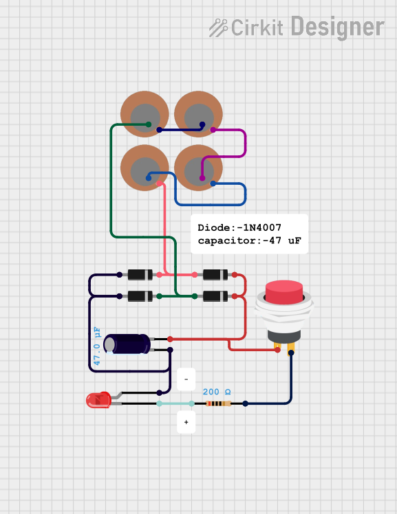
This document provides a detailed overview of a circuit consisting of various components including piezo sensors, diodes, an electrolytic capacitor, an LED, a push switch, and a resistor. The document includes a component list, wiring details, and code documentation.
Component List
Piezo Sensor
- Pins: +, -
- Description: Converts mechanical stress into electrical signals.
Diode
- Pins: cathode, anode
- Description: Allows current to flow in one direction only.
Electrolytic Capacitor
- Pins: -, +
- Description: Stores electrical energy.
- Properties:
- Capacitance: 0.000047 Farads
LED: Two Pin (red)
- Pins: cathode, anode
- Description: Emits light when current flows through it.
2Pin Push Switch
- Pins: Input +, Output +
- Description: Allows or interrupts the flow of current when pressed.
Resistor
- Pins: pin1, pin2
- Description: Limits the flow of electrical current.
- Properties:
- Resistance: 200 Ohms
Comment
- Description: Used for adding notes or comments in the circuit.
Wiring Details
Piezo Sensor
Instance 1:
- + Pin: Connected to the anode of Diode (Instance 3) and cathode of Diode (Instance 2).
- - Pin: Connected to the + pin of Piezo Sensor (Instance 2).
Instance 2:
- + Pin: Connected to the - pin of Piezo Sensor (Instance 1).
- - Pin: Connected to the + pin of Piezo Sensor (Instance 3).
Instance 3:
- + Pin: Connected to the - pin of Piezo Sensor (Instance 2).
- - Pin: Connected to the + pin of Piezo Sensor (Instance 4).
Instance 4:
- + Pin: Connected to the - pin of Piezo Sensor (Instance 3).
- - Pin: Connected to the anode of Diode (Instance 1) and cathode of Diode (Instance 4).
Diode
Instance 1:
- Cathode: Connected to the anode of Diode (Instance 3) and + pin of Piezo Sensor (Instance 1).
- Anode: Connected to the anode of Diode (Instance 4), anode of LED, and - pin of Electrolytic Capacitor.
Instance 2:
- Cathode: Connected to the anode of Diode (Instance 4) and + pin of Piezo Sensor (Instance 1).
- Anode: Connected to the cathode of Diode (Instance 3) and - pin of Piezo Sensor (Instance 3).
Instance 3:
- Cathode: Connected to the anode of Diode (Instance 1) and + pin of Piezo Sensor (Instance 1).
- Anode: Connected to the cathode of Diode (Instance 2) and - pin of Piezo Sensor (Instance 3).
Instance 4:
- Cathode: Connected to the anode of Diode (Instance 1) and + pin of Piezo Sensor (Instance 1).
- Anode: Connected to the cathode of Diode (Instance 2) and - pin of Piezo Sensor (Instance 3).
Electrolytic Capacitor
- - Pin: Connected to the anode of Diode (Instance 1).
- + Pin: Connected to the cathode of Diode (Instance 4).
LED: Two Pin (red)
- Cathode: Connected to pin1 of Resistor.
- Anode: Connected to the anode of Diode (Instance 1).
2Pin Push Switch
- Input +: Connected to the cathode of Diode (Instance 4).
- Output +: Connected to pin2 of Resistor.
Resistor
- Pin1: Connected to the cathode of LED.
- Pin2: Connected to the Output + pin of 2Pin Push Switch.
Code Documentation
No microcontroller code is provided for this circuit.
This document provides a comprehensive overview of the circuit, including detailed wiring information for each component.