
Arduino Mega 2560-Based Battery-Powered Robotic Car with Ultrasonic and IR Sensors
View and Edit Project In Cirkit Designer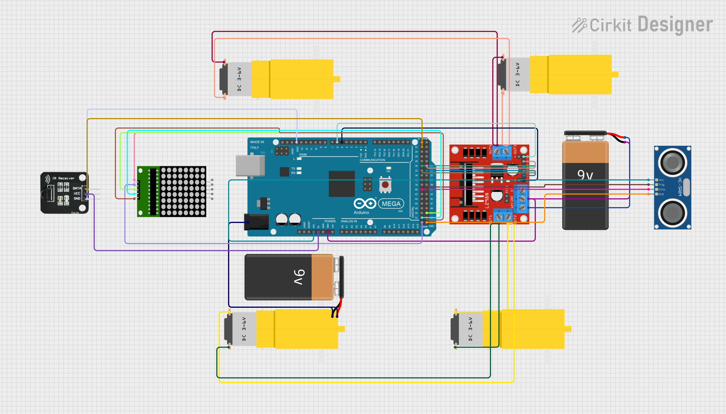
Circuit Documentation
Summary
This circuit involves an Arduino Mega 2560 microcontroller, an L298N DC motor driver, four hobby motors, a 9V battery, an HC-SR04 ultrasonic sensor, an IR receiver, and an 8x8 LED matrix. The Arduino Mega 2560 serves as the central controller, interfacing with the motor driver to control the motors, reading data from the ultrasonic sensor and IR receiver, and driving the LED matrix.
Component List
Arduino Mega 2560
- Description: A microcontroller board based on the ATmega2560.
- Pins: IOREF, RESET, 3V3, 5V, GND, VIN, A0-A15, D0-D53, AREF, SDA, SCL, 6swdw
L298N DC Motor Driver
- Description: A dual H-Bridge motor driver module.
- Pins: OUT1, OUT2, 12V, GND, 5V, OUT3, OUT4, 5V-ENA-JMP-I, 5V-ENA-JMP-O, +5V-J1, +5V-J2, ENA, IN1, IN2, IN3, IN4, ENB
Motor amarillo motorreductor hobby
- Description: A small DC motor with a gearbox.
- Pins: vcc, GND
9V Battery
- Description: A standard 9V battery.
- Pins: -, +
HC-SR04 Ultrasonic Sensor
- Description: An ultrasonic distance sensor.
- Pins: VCC, TRIG, ECHO, GND
IR Receiver
- Description: An infrared receiver module.
- Pins: DATA, VCC, GND
8x8 LED Matrix
- Description: An 8x8 LED matrix display.
- Pins: vcc, DIN, clk, CS, Gnd, gnd, CLK
Wiring Details
Arduino Mega 2560
- 3V3 connected to VCC of HC-SR04 Ultrasonic Sensor
- 5V connected to VCC of IR Receiver and vcc of 8x8 LED Matrix
- GND connected to:
- - of 9V Battery
- GND of L298N DC Motor Driver
- GND of IR Receiver
- Gnd of 8x8 LED Matrix
- GND of HC-SR04 Ultrasonic Sensor
- D5 PWM connected to ENA of L298N DC Motor Driver
- D6 PWM connected to ENB of L298N DC Motor Driver
- D52 connected to clk of 8x8 LED Matrix
- D40 connected to ECHO of HC-SR04 Ultrasonic Sensor
- D32 connected to IN2 of L298N DC Motor Driver
- D30 connected to IN3 of L298N DC Motor Driver
- D22 connected to DATA of IR Receiver
- D53 connected to CS of 8x8 LED Matrix
- D51 connected to DIN of 8x8 LED Matrix
- D41 connected to TRIG of HC-SR04 Ultrasonic Sensor
- D33 connected to IN1 of L298N DC Motor Driver
- D31 connected to IN4 of L298N DC Motor Driver
- 6swdw connected to - and + of 9V Battery
L298N DC Motor Driver
- OUT1 connected to GND of two hobby motors
- OUT2 connected to vcc of two hobby motors
- OUT3 connected to GND of two hobby motors
- OUT4 connected to vcc of two hobby motors
- 12V connected to + of 9V Battery
HC-SR04 Ultrasonic Sensor
- VCC connected to 3V3 of Arduino Mega 2560
- TRIG connected to D41 of Arduino Mega 2560
- ECHO connected to D40 of Arduino Mega 2560
- GND connected to GND of Arduino Mega 2560
IR Receiver
- DATA connected to D22 of Arduino Mega 2560
- VCC connected to 5V of Arduino Mega 2560
- GND connected to GND of Arduino Mega 2560
8x8 LED Matrix
- vcc connected to 5V of Arduino Mega 2560
- DIN connected to D51 of Arduino Mega 2560
- clk connected to D52 of Arduino Mega 2560
- CS connected to D53 of Arduino Mega 2560
- Gnd connected to GND of Arduino Mega 2560
Hobby Motors
- GND of two motors connected to OUT1 of L298N DC Motor Driver
- vcc of two motors connected to OUT2 of L298N DC Motor Driver
- GND of two motors connected to OUT3 of L298N DC Motor Driver
- vcc of two motors connected to OUT4 of L298N DC Motor Driver
9V Battery
- - connected to GND of Arduino Mega 2560
- + connected to 12V of L298N DC Motor Driver
Documented Code
Arduino Mega 2560 Code
void setup() {
  // put your setup code here, to run once:

}

void loop() {
  // put your main code here, to run repeatedly:

}
This code is a basic template for the Arduino Mega 2560. The setup() function is used to initialize any settings or configurations, and the loop() function contains the main code that runs repeatedly.