
ESP32-Based Water Level Monitoring System with I2C LCD and Buzzer
View and Edit Project In Cirkit Designer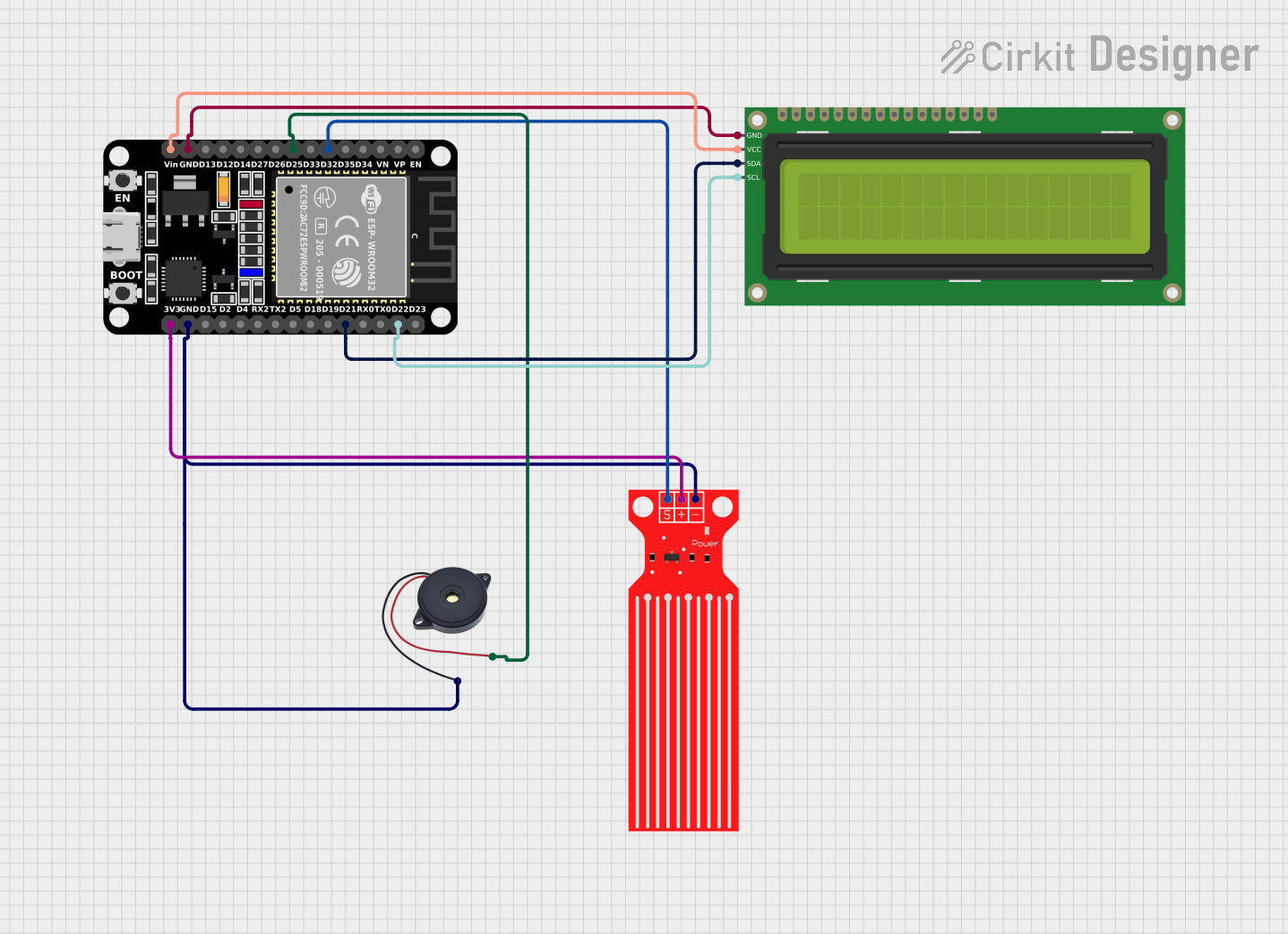
Water Level Monitoring System Documentation
Summary
This document provides a detailed overview of a water level monitoring system. The system uses an ESP32 microcontroller to read data from a water level sensor, display the water level on a 16x2 I2C LCD, and activate a buzzer when the water level is low.
Component List
ESP32 (30 pin)
- Description: A powerful microcontroller with built-in Wi-Fi and Bluetooth capabilities.
- Pins: EN, VP, VN, D34, D35, D32, D33, D25, D26, D27, D14, D12, D13, GND, Vin, D23, D22, TX0, RX0, D21, D19, D18, D5, TX2, RX2, D4, D2, D15, 3V3
Buzzer
- Description: An audio signaling device that emits sound when activated.
- Pins: GND, IN
16x2 I2C LCD
- Description: A 16x2 character LCD display with I2C interface.
- Pins: GND, VCC, SDA, SCL
Water Level Sensor
- Description: A sensor that measures the water level and outputs an analog signal.
- Pins: SIG, VCC, GND
Wiring Details
ESP32 (30 pin)
- D32: Connected to SIG of Water Level Sensor
- D25: Connected to IN of Buzzer
- GND: Connected to GND of 16x2 I2C LCD, GND of Water Level Sensor, and GND of Buzzer
- Vin: Connected to VCC of 16x2 I2C LCD
- D22: Connected to SCL of 16x2 I2C LCD
- D21: Connected to SDA of 16x2 I2C LCD
- 3V3: Connected to VCC of Water Level Sensor
Buzzer
- GND: Connected to GND of ESP32
- IN: Connected to D25 of ESP32
16x2 I2C LCD
- GND: Connected to GND of ESP32
- VCC: Connected to Vin of ESP32
- SDA: Connected to D21 of ESP32
- SCL: Connected to D22 of ESP32
Water Level Sensor
- SIG: Connected to D32 of ESP32
- VCC: Connected to 3V3 of ESP32
- GND: Connected to GND of ESP32
Code Documentation
ESP32 Microcontroller Code
/*
 * This Arduino sketch is designed to control a water level monitoring system.
 * The system uses an ESP32 microcontroller to read data from a water level
 * sensor, display the water level on a 16x2 I2C LCD, and activate a buzzer
 * when the water level is low.
 */

#include <Wire.h>
#include <LiquidCrystal_I2C.h>

// Pin definitions
#define WATER_LEVEL_PIN 32
#define BUZZER_PIN 25
#define LCD_ADDRESS 0x27
#define LCD_COLUMNS 16
#define LCD_ROWS 2

// Create LCD object
LiquidCrystal_I2C lcd(LCD_ADDRESS, LCD_COLUMNS, LCD_ROWS);

void setup() {
  // Initialize serial communication
  Serial.begin(115200);

  // Initialize LCD
  lcd.begin(LCD_COLUMNS, LCD_ROWS);
  lcd.backlight();

  // Initialize pins
  pinMode(WATER_LEVEL_PIN, INPUT);
  pinMode(BUZZER_PIN, OUTPUT);

  // Display initial message
  lcd.setCursor(0, 0);
  lcd.print("Water Level:");
}

void loop() {
  // Read water level sensor
  int waterLevel = analogRead(WATER_LEVEL_PIN);

  // Display water level on LCD
  lcd.setCursor(0, 1);
  lcd.print(waterLevel);
  lcd.print(" "); // Clear any extra characters

  // Check if water level is low
  if (waterLevel < 500) { // Adjust threshold as needed
    digitalWrite(BUZZER_PIN, HIGH); // Activate buzzer
  } else {
    digitalWrite(BUZZER_PIN, LOW); // Deactivate buzzer
  }

  // Delay for a short period
  delay(1000);
}
This code initializes the ESP32 microcontroller, sets up the pins, and continuously reads the water level from the sensor. The water level is displayed on the 16x2 I2C LCD, and the buzzer is activated if the water level falls below a specified threshold.