Cirkit Designer
Your all-in-one circuit design IDE
Home /
Project Documentation
Arduino UNO-Based Smart Sensor System with Buzzer and Motor Control
Circuit Documentation
Summary
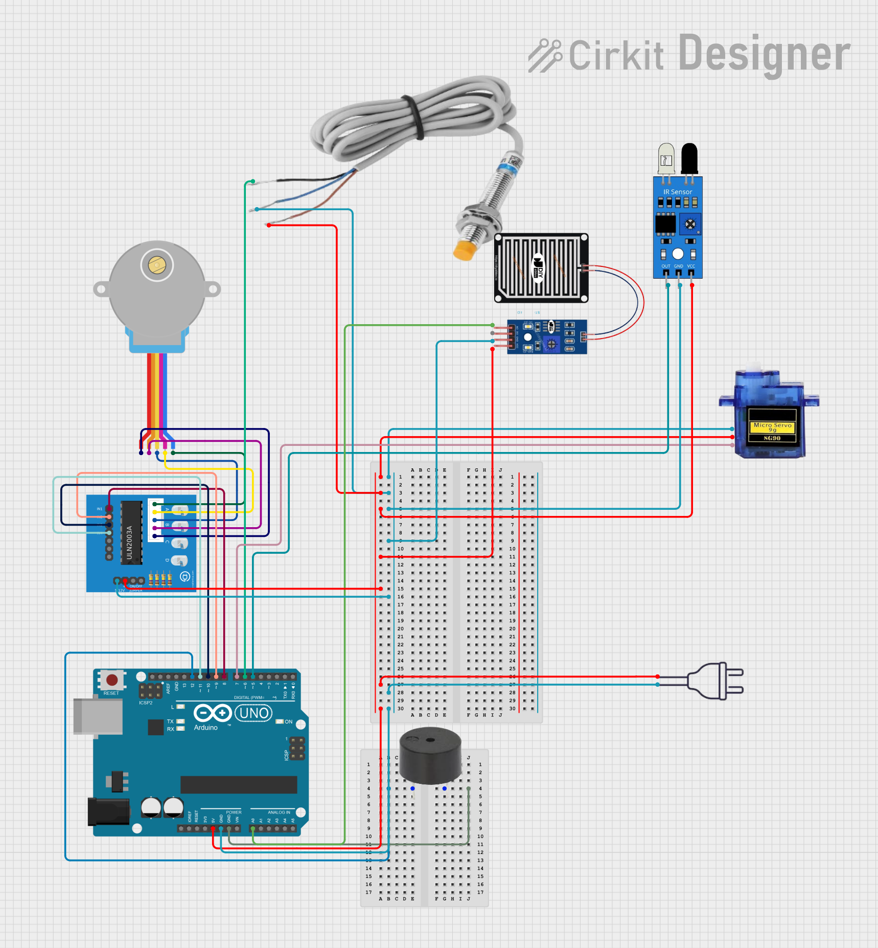
This document provides a detailed overview of a circuit involving an Arduino UNO microcontroller, a buzzer, a micro servo, a stepper motor, various sensors, and a ULN2003A breakout board. The circuit is designed to interface with multiple sensors and actuators, controlled by the Arduino UNO. The document includes a component list, wiring details, and the embedded code used in the microcontroller.
Component List
Arduino UNO
- Description: A microcontroller board based on the ATmega328P.
- Pins: UNUSED, IOREF, Reset, 3.3V, 5V, GND, Vin, A0, A1, A2, A3, A4, A5, SCL, SDA, AREF, D13, D12, D11, D10, D9, D8, D7, D6, D5, D4, D3, D2, D1, D0
Buzzer
- Description: A simple piezoelectric buzzer.
- Pins: PIN, GND
Micro Servo 9G
- Description: A small servo motor used for precise control of angular position.
- Pins: GND, +5V, PWM
Adafruit Gear-Reduced Stepper Motor (small)
- Description: A small stepper motor with gear reduction for increased torque.
- Pins: RED, ORANGE, YELLOW, PINK, BLUE
ULN2003A Breakout Board
- Description: A breakout board for the ULN2003A Darlington transistor array, used to drive the stepper motor.
- Pins: In 1, In 2, In 3, In 4, In 5, In 6, In 7, 0V, +5V, ON/OFF jumper switch, BLUE wire, PINK wire, YELLOW wire, ORANGE wire, RED wire
Inductive Sensor
- Description: A sensor used to detect metallic objects without physical contact.
- Pins: black, blue, red
IR Sensor
- Description: An infrared sensor used for object detection.
- Pins: out, gnd, vcc
Rain Sensor
- Description: A sensor used to detect the presence of rain.
- Pins: AO, DO, GRD, VCC
Power 220V
- Description: A power source providing 220V AC.
- Pins: hot wire, neutral wire
Wiring Details
Arduino UNO
- 5V: Connected to +5V of Micro Servo 9G, red of Inductive Sensor, vcc of IR Sensor, VCC of Rain Sensor, +5V of ULN2003A Breakout Board, hot wire of Power 220V
- GND: Connected to GND of Buzzer, GND of Micro Servo 9G, blue of Inductive Sensor, gnd of IR Sensor, GRD of Rain Sensor, 0V of ULN2003A Breakout Board, neutral wire of Power 220V
- D12: Connected to PIN of Buzzer
- A0: Connected to AO of Rain Sensor
- D11: Connected to In 4 of ULN2003A Breakout Board
- D10: Connected to In 3 of ULN2003A Breakout Board
- D9: Connected to In 2 of ULN2003A Breakout Board
- D8: Connected to In 1 of ULN2003A Breakout Board
- D7: Connected to PWM of Micro Servo 9G
- D6: Connected to black of Inductive Sensor
- D5: Connected to out of IR Sensor
Buzzer
- PIN: Connected to D12 of Arduino UNO
- GND: Connected to GND of Arduino UNO
Micro Servo 9G
- +5V: Connected to 5V of Arduino UNO
- GND: Connected to GND of Arduino UNO
- PWM: Connected to D7 of Arduino UNO
Adafruit Gear-Reduced Stepper Motor (small)
- RED: Connected to RED wire of ULN2003A Breakout Board
- ORANGE: Connected to ORANGE wire of ULN2003A Breakout Board
- YELLOW: Connected to YELLOW wire of ULN2003A Breakout Board
- PINK: Connected to PINK wire of ULN2003A Breakout Board
- BLUE: Connected to BLUE wire of ULN2003A Breakout Board
ULN2003A Breakout Board
- In 1: Connected to D8 of Arduino UNO
- In 2: Connected to D9 of Arduino UNO
- In 3: Connected to D10 of Arduino UNO
- In 4: Connected to D11 of Arduino UNO
- +5V: Connected to 5V of Arduino UNO
- 0V: Connected to GND of Arduino UNO
- RED wire: Connected to RED of Adafruit Gear-Reduced Stepper Motor
- ORANGE wire: Connected to ORANGE of Adafruit Gear-Reduced Stepper Motor
- YELLOW wire: Connected to YELLOW of Adafruit Gear-Reduced Stepper Motor
- PINK wire: Connected to PINK of Adafruit Gear-Reduced Stepper Motor
- BLUE wire: Connected to BLUE of Adafruit Gear-Reduced Stepper Motor
Inductive Sensor
- red: Connected to 5V of Arduino UNO
- blue: Connected to GND of Arduino UNO
- black: Connected to D6 of Arduino UNO
IR Sensor
- vcc: Connected to 5V of Arduino UNO
- gnd: Connected to GND of Arduino UNO
- out: Connected to D5 of Arduino UNO
Rain Sensor
- VCC: Connected to 5V of Arduino UNO
- GRD: Connected to GND of Arduino UNO
- AO: Connected to A0 of Arduino UNO
Power 220V
- hot wire: Connected to 5V of Arduino UNO
- neutral wire: Connected to GND of Arduino UNO
Documented Code
Arduino UNO Code
void setup() {
  // put your setup code here, to run once:

}

void loop() {
  // put your main code here, to run repeatedly:

}
This code is a basic template for the Arduino UNO, with empty setup and loop functions. The setup function runs once when the microcontroller is powered on or reset, and the loop function runs continuously after the setup function completes.