Cirkit Designer
Your all-in-one circuit design IDE
Home /
Project Documentation
Arduino Mega 2560 Brushless Motor Controller with ESC and Microzone MC7RB
Circuit Documentation
Summary
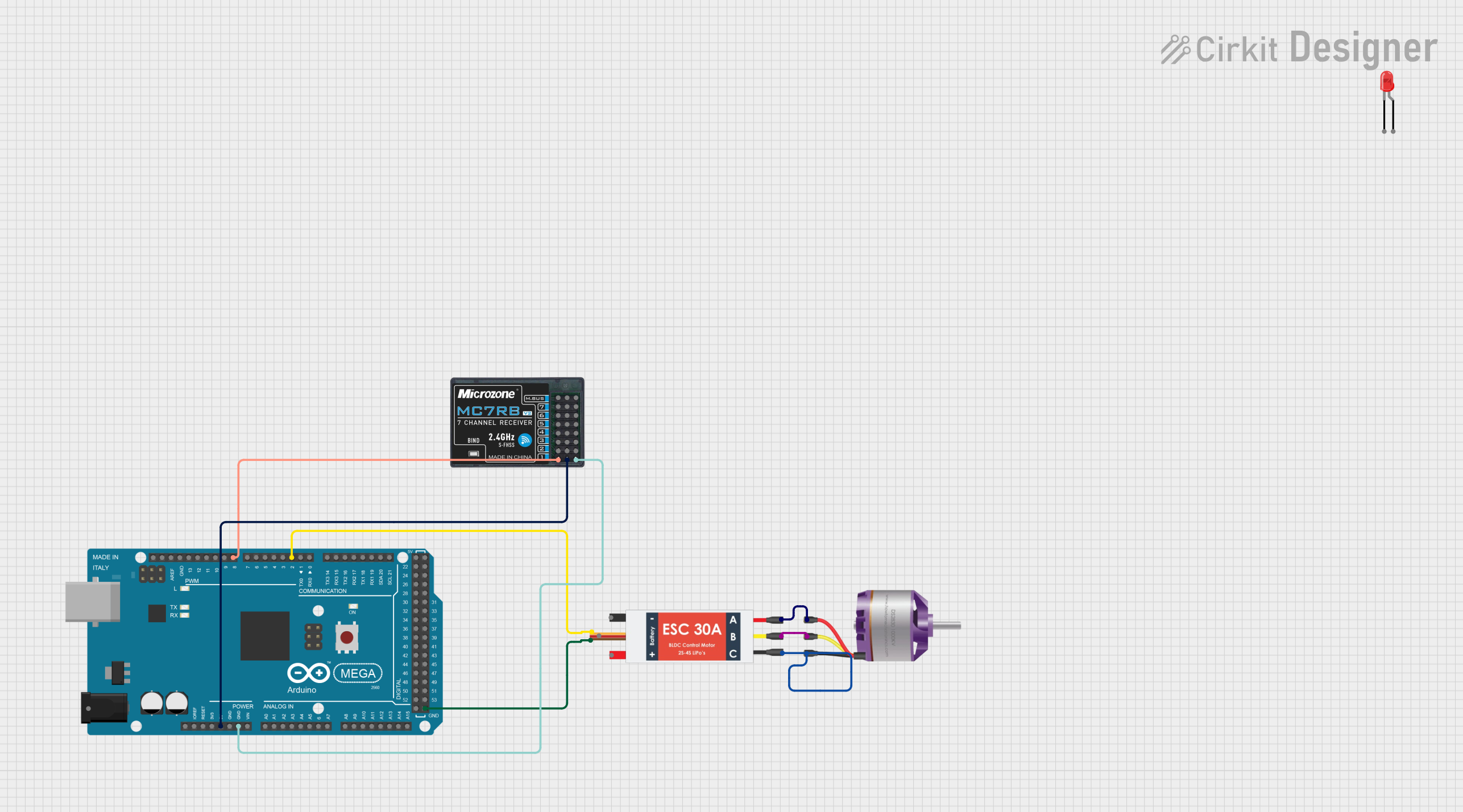
This document provides a detailed overview of a circuit that includes an Arduino Mega 2560 microcontroller, a brushless motor, a Microzone MC7RB, an Electronic Speed Controller (ESC), and a red LED. The circuit is designed to control the brushless motor and the LED using the Arduino Mega 2560.
Component List
Arduino Mega 2560
- Description: A microcontroller board based on the ATmega2560.
- Pins: IOREF, RESET, 3V3, 5V, GND, VIN, A0-A15, D21/SCL, D20/SDA, D19/RX1, D18/TX1, D17 PWM/RX2, D16 PWM/TX2, D15/RX3, D14/TX3, D0 RX0, D1 TX0, D2 PWM, D3 PWM, D4 PWM, D5 PWM, D6 PWM, D7 PWM, D8 PWM, D9 PWM, D10 PWM, D11 PWM, D12 PWM, D13 PWM, AREF, SDA, SCL, D52, D50, D48, D46, D44, D42, D40, D38, D36, D34, D32, D30, D28, D26, D24, D22, D53, D51, D49, D47, D45, D43, D41, D39, D37, D35, D33, D31, D29, D27, D25, D23, 6swdw.
Brushless Motor
- Description: A motor that operates using an electronic speed controller.
- Pins: L1, L2, L3.
Microzone MC7RB
- Description: A receiver module.
- Pins: Signal, VCC, GND, PWM.
Electronic Speed Controller (ESC)
- Description: A device used to control the speed of the brushless motor.
- Pins: Battery VCC, Battery GND, Signal, 5v out, GND out, M1, M2, M3.
LED: Two Pin (red)
- Description: A red LED with two pins.
- Pins: cathode, anode.
Wiring Details
Arduino Mega 2560
- 5V is connected to VCC of the Microzone MC7RB.
- GND is connected to GND of the Microzone MC7RB.
- D2 PWM is connected to Signal of the Electronic Speed Controller (ESC).
- D8 PWM is connected to PWM of the Microzone MC7RB.
- GND is connected to GND out of the Electronic Speed Controller (ESC).
Brushless Motor
- L1 is connected to M1 of the Electronic Speed Controller (ESC).
- L2 is connected to M2 of the Electronic Speed Controller (ESC).
- L3 is connected to M3 of the Electronic Speed Controller (ESC).
Microzone MC7RB
- VCC is connected to 5V of the Arduino Mega 2560.
- GND is connected to GND of the Arduino Mega 2560.
- PWM is connected to D8 PWM of the Arduino Mega 2560.
Electronic Speed Controller (ESC)
- Signal is connected to D2 PWM of the Arduino Mega 2560.
- GND out is connected to GND of the Arduino Mega 2560.
- M1 is connected to L1 of the Brushless Motor.
- M2 is connected to L2 of the Brushless Motor.
- M3 is connected to L3 of the Brushless Motor.
LED: Two Pin (red)
- No connections specified in the provided net list.
Documented Code
Arduino Mega 2560 Code
void setup() {
  // put your setup code here, to run once:

}

void loop() {
  // put your main code here, to run repeatedly:

}
Additional Documentation
No additional documentation provided.