
Arduino Nano Controlled LED Light Show with 74HC595 Shift Register and Current Sensing
View and Edit Project In Cirkit Designer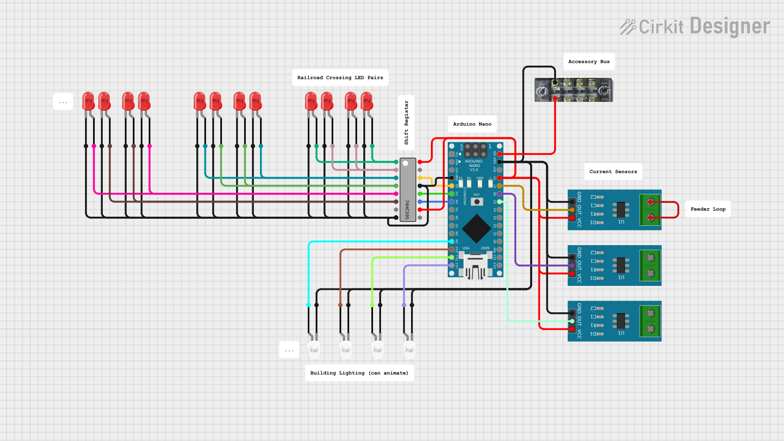
Circuit Documentation
Summary
This circuit primarily consists of an Arduino Nano microcontroller interfaced with a 74HC595 shift register and multiple LEDs (both red and white). The 74HC595 is used to expand the number of digital output pins available from the Arduino Nano, allowing for control of multiple LEDs with fewer Arduino pins. Additionally, there are current sensors in the circuit, which are likely used to monitor the current through certain parts of the circuit.
Component List
Microcontroller
- Arduino Nano: A compact microcontroller board based on the ATmega328P, featuring digital and analog I/O pins.
Shift Register
- 74HC595: An 8-bit serial-in, serial or parallel-out shift register with output latches; used for pin expansion.
LEDs
- LED: Two Pin (red): A basic red light-emitting diode for indication or display purposes.
- LED: Two Pin (white): A basic white light-emitting diode for indication or display purposes.
Current Sensors
- Current Sensor 5A: A sensor used to measure up to 5A of current flowing through the circuit.
Terminal Block
- terminalblock-04-01: A 4-position terminal block for making easy connections to the board.
Comments
- Comment: Placeholder for user comments or notes in the circuit design.
Wiring Details
Arduino Nano
- Digital Pins (D2, D3, D4): Connected to the 74HC595 shift register for serial data input and control.
- Digital Pins (D9, D10, D11/MOSI, D12/MISO): Connected to white LEDs for direct control.
- Analog Pins (A5, A6, A7): Connected to the outputs of the current sensors.
- Power (5V, GND): Provide power to the 74HC595 shift register and current sensors.
- Power (VIN): Connected to the terminal block for power input.
74HC595 Shift Register
- Data Pin (DS): Receives serial data from Arduino Nano (D2).
- Latch Pin (ST_CP/RCLK): Latch control from Arduino Nano (D3).
- Clock Pin (SH_CP/SRCLK): Shift register clock from Arduino Nano (D4).
- Output Enable (OE): Grounded to enable outputs.
- Master Reset (MR/SRCLR): Connected to 5V for normal operation.
- Outputs (Q0-Q7): Connected to the anodes of red LEDs.
- Power (VCC, GND): Powered by the Arduino Nano 5V and GND pins.
LEDs (Red and White)
- Anode: Connected to the 74HC595 outputs or directly to Arduino Nano pins for red and white LEDs, respectively.
- Cathode: Commonly connected to GND.
Current Sensor 5A
- OUT: Connected to Arduino Nano analog pins (A5, A6, A7) to read current measurements.
- Power (VCC, GND): Powered by the Arduino Nano 5V and GND pins.
Terminal Block
- Pin 2: Connected to Arduino Nano VIN for power input.
- Pin 1: Common ground connection.
Documented Code
Arduino Nano - sketch.ino
void setup() {
  // put your setup code here, to run once:

}

void loop() {
  // put your main code here, to run repeatedly:

}
Arduino Nano - documentation.txt
(No additional documentation provided)
This documentation provides an overview of the circuit components, their wiring, and the initial code structure for the Arduino Nano. Further details, such as the purpose of each part in the circuit and the specific functionality of the code, would be necessary to fully understand and utilize this circuit.