
Arduino UNO Multi-Sensor Monitoring System with Bluetooth Connectivity
View and Edit Project In Cirkit Designer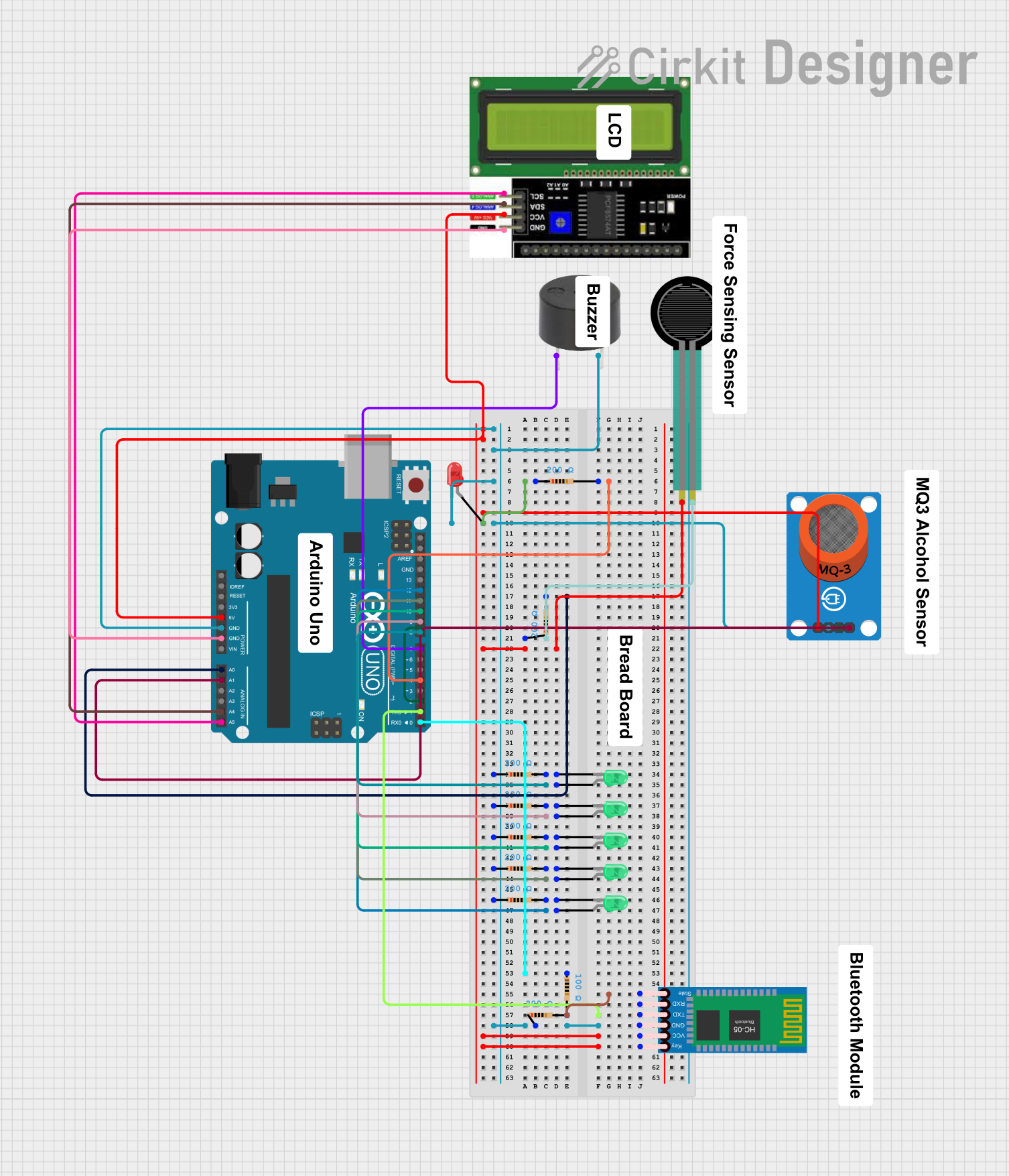
Circuit Documentation
Summary
This document provides a detailed overview of an electronic circuit that includes an Arduino UNO as the central microcontroller. The circuit features various components such as LEDs, a buzzer, an LCD I2C display, a force sensing resistor, an MQ-3 alcohol sensor, and an HC-05 Bluetooth module. The circuit is designed to interface with sensors and output devices, allowing for data acquisition, user interaction, and wireless communication capabilities.
Component List
Arduino UNO
- Microcontroller board based on the ATmega328P
- Features digital I/O pins, analog input pins, and power pins
Buzzer
- An electromechanical component that produces sound when energized
LED: Two Pin (Red)
- A red light-emitting diode that emits light when a forward current passes through it
LED: Two Pin (Green)
- A green light-emitting diode that emits light when a forward current passes through it
LCD I2C Display
- A liquid crystal display with an I2C interface for displaying text and numbers
Force Sensing Resistor
- A sensor that changes its resistance based on the force applied to its surface
MQ-3 Breakout
- An alcohol sensor module designed to detect alcohol vapor in the air
HC-05 Bluetooth Module
- A wireless communication module that enables Bluetooth connectivity
Resistor (200 Ohms)
- A passive component used to limit current or divide voltages in the circuit
Resistor (100 Ohms)
- A passive component with a lower resistance value, used for similar purposes as the 200 Ohm resistor
Wiring Details
Arduino UNO
5VandGNDpins provide power to the HC-05 Bluetooth module, MQ-3 sensor, and force sensing resistor- Digital pins
D0toD12are used to interface with the buzzer, LEDs, and the MQ-3 sensor - Analog pins
A0andA1are connected to the force sensing resistor and MQ-3 sensor respectively - I2C pins
A4(SDA) andA5(SCL) are connected to the LCD I2C display
Buzzer
- Connected to digital pin
D7on the Arduino UNO for control - Grounded through a common ground connection
LEDs (Red and Green)
- Red LED anode connected to a 200 Ohm resistor, which is then connected to digital pin
D4on the Arduino UNO - Green LEDs anodes are connected to digital pins
D8toD12on the Arduino UNO - All LED cathodes are grounded through a common ground connection
LCD I2C Display
VCCconnected to the5Vpin on the Arduino UNOGNDconnected to a common groundSDAandSCLconnected toA4andA5on the Arduino UNO for I2C communication
Force Sensing Resistor
- One pin connected to the
A0pin on the Arduino UNO through a 200 Ohm resistor - The other pin connected to the
5Vsupply
MQ-3 Breakout
VCCconnected to the5Vpin on the Arduino UNOGNDconnected to a common groundAOconnected to theA1pin on the Arduino UNO for analog outputDOconnected to digital pinD2on the Arduino UNO for digital output
HC-05 Bluetooth Module
VCCconnected to the5Vpin on the Arduino UNOGNDconnected to a common groundTXDconnected to digital pinD1on the Arduino UNO for transmitting dataStateconnected to a 100 Ohm resistor, which is then connected to a common ground
Resistor (200 Ohms)
- Used in series with the red LED and the force sensing resistor
- Used in series with each green LED for current limiting
Resistor (100 Ohms)
- Used in series with the
Statepin of the HC-05 Bluetooth module
Documented Code
void setup() {
  // put your setup code here, to run once:

}

void loop() {
  // put your main code here, to run repeatedly:

}
The provided code is a template with empty setup() and loop() functions, which are the entry points for Arduino sketches. The setup() function is called once when the sketch starts and is used for initializing settings or pin modes. The loop() function is called repeatedly and contains the main logic of the sketch. The actual implementation details need to be filled in based on the specific requirements of the circuit's functionality.