Cirkit Designer
Your all-in-one circuit design IDE
Home /
Project Documentation
Arduino-Controlled Robotic Vehicle with Flame Sensors and Air Pump
Circuit Documentation
Summary
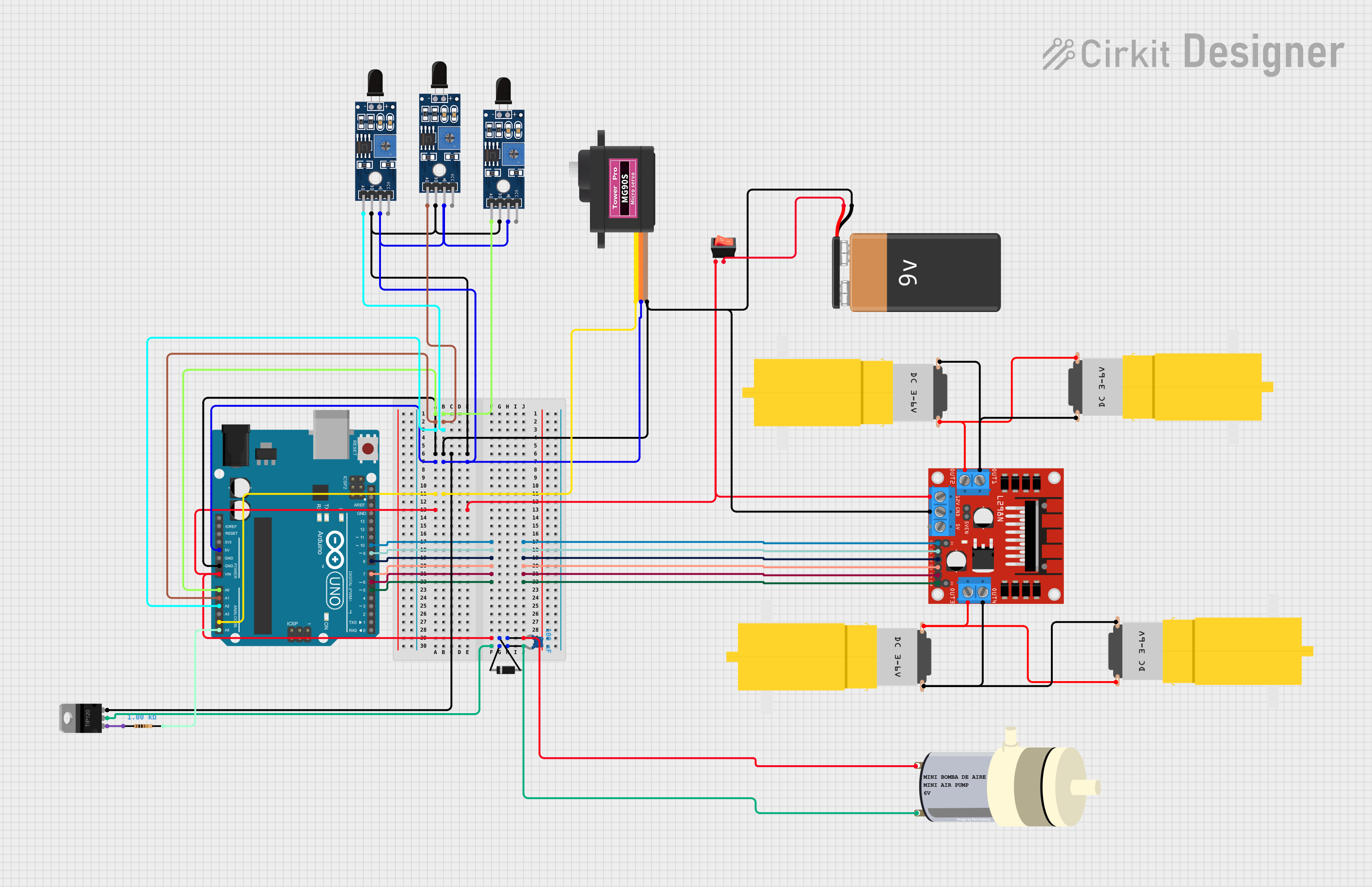
The circuit in question is designed to control a set of motors and a mini air pump, with inputs from flame sensors and a servo motor for directional control. The brain of the circuit is an Arduino UNO microcontroller, which processes sensor inputs and controls the actuators accordingly. The circuit includes a motor driver (L298N) to manage the high-current demands of the motors, and a Darlington transistor (TIP120) to control the mini air pump. Power is supplied by a 9V battery, and a rocker switch is used to turn the circuit on and off. A diode and a ceramic capacitor are included for protection and noise reduction.
Component List
- Motor Amarillo Motorreductor Hobby: A DC motor used for driving mechanisms.
- L298N DC Motor Driver: An integrated circuit used for controlling DC motors with direction and speed control.
- Mini Air Pump: A small pump used for air displacement.
- Sensor SHT113 Flame: A flame sensor used for detecting fire or flame presence.
- Arduino UNO: A microcontroller board based on the ATmega328P, used for controlling the logic of the circuit.
- 9V Battery: A standard 9V battery used as the power source for the circuit.
- Ceramic Capacitor: A capacitor used for noise reduction and voltage smoothing.
- Servomotor MG90S: A small servo motor used for precise control of angular position.
- Rocker Switch: A switch used to turn the circuit on and off.
- Diode: A component used to ensure current flows in only one direction, providing protection against reverse polarity.
- TIP120 Hi-Current Darlington Transistor: A transistor used for controlling high current loads.
- Resistor: A component used to limit current or divide voltages in the circuit.
Wiring Details
Motor Amarillo Motorreductor Hobby
- VCC: Connected to the output of the L298N motor driver.
- GND: Connected to the ground net of the circuit.
L298N DC Motor Driver
- OUT1, OUT2, OUT3, OUT4: Connected to the motors.
- 12V: Connected to the 9V battery through a rocker switch.
- GND: Connected to the ground net of the circuit.
- 5V: Not connected in this circuit.
- ENA, ENB: Connected to the Arduino UNO for speed control.
- IN1, IN2, IN3, IN4: Connected to the Arduino UNO for direction control.
Mini Air Pump
- PIN1, PIN2: Controlled by the TIP120 transistor and connected to the power supply through a diode and capacitor.
Sensor SHT113 Flame
- A0, D0: Connected to the analog pins of the Arduino UNO for flame detection.
- GND: Connected to the ground net of the circuit.
- VCC: Connected to the 5V output of the Arduino UNO.
Arduino UNO
- Digital and Analog Pins: Connected to various components for control and sensing.
- 5V, GND: Power supply for the sensors and servo motor.
- Vin: Connected to the 12V input of the L298N motor driver.
9V Battery
- +: Connected to the rocker switch.
- -: Connected to the ground net of the circuit.
Ceramic Capacitor
- Pin0, Pin1: Connected across the power supply of the mini air pump for noise reduction.
Servomotor MG90S
- SIG: Controlled by an analog pin of the Arduino UNO.
- VCC: Connected to the 5V output of the Arduino UNO.
- GND: Connected to the ground net of the circuit.
Rocker Switch
- Input: Connected to the positive terminal of the 9V battery.
- Output: Connected to the 12V input of the L298N motor driver.
Diode
- Anode: Connected to the positive terminal of the 9V battery.
- Cathode: Connected to the mini air pump and TIP120 transistor.
TIP120 Hi-Current Darlington Transistor
- BASE: Controlled by the Arduino UNO through a resistor.
- COLLECTOR: Connected to the mini air pump.
- EMITTER: Connected to the ground net of the circuit.
Resistor
- Pin1, Pin2: Connected between the Arduino UNO and the base of the TIP120 transistor to limit the base current.
Documented Code
#define enA 10    // Enable1 L298 Pin enA (Motor1 Speed Control)
#define in1 9     // Motor1 L298 Pin in1 (Motor1 Forward)
#define in2 8     // Motor1 L298 Pin in2 (Motor1 Backward)
#define in3 7     // Motor2 L298 Pin in3 (Motor2 Forward)
#define in4 6     // Motor2 L298 Pin in4 (Motor2 Backward)
#define enB 5     // Enable2 L298 Pin enB (Motor2 Speed Control)
#define ir_R A0   // Right Infrared sensor
#define ir_F A1   // Front Infrared sensor
#define ir_L A2   // Left Infrared sensor
#define servo A4  // Servo Motor pin
#define pump A5   // Pump control pin

int Speed = 160;  // Duty Cycle (0 to 255) for motor speed control
int s1, s2, s3;   // Variables to store sensor readings

void setup() {
  Serial.begin(9600);            // Start serial communication at 9600 bps
  pinMode(ir_R, INPUT);          // Set right sensor as input
  pinMode(ir_F, INPUT);          // Set front sensor as input
  pinMode(ir_L, INPUT);          // Set left sensor as input
  pinMode(enA, OUTPUT);          // Motor1 speed control
  pinMode(in1, OUTPUT);          // Motor1 forward
  pinMode(in2, OUTPUT);          // Motor1 backward
  pinMode(in3, OUTPUT);          // Motor2 forward
  pinMode(in4, OUTPUT);          // Motor2 backward
  pinMode(enB, OUTPUT);          // Motor2 speed control
  pinMode(servo, OUTPUT);        // Servo motor control
  pinMode(pump, OUTPUT);         // Pump control

  // Initial servo movements
  for (int angle = 90; angle <= 140; angle += 5) {
    servoPulse(servo, angle);
  }
  for (int angle = 140; angle >= 40; angle -= 5) {
    servoPulse(servo, angle);
  }
  for (int angle = 40; angle <= 95; angle += 5) {
    servoPulse(servo, angle);
  }

  // Set initial motor speeds
  analogWrite(enA, Speed);  // Set Motor1 speed
  analogWrite(enB, Speed);  // Set Motor2 speed
  delay(500);
}

void loop() {
  s1 = analogRead(ir_R);  // Read right sensor
  s2 = analogRead(ir_F);  // Read front sensor
  s3 = analogRead(ir_L);  // Read left sensor

  // Display sensor readings on the serial monitor
  Serial.print(s1); Serial.print("\t");
  Serial.print(s2); Serial.print("\t");
  Serial.println(s3);
  delay(50);

  // Automated control based on sensor input
  if (s1 < 250) {
    Stop();
    digitalWrite(pump, 1);
    for (int angle = 90; angle >= 40; angle -= 3) {
      servoPulse(servo, angle);
    }
    for (int angle = 40; angle <= 90; angle += 3) {
      servoPulse(servo, angle);
    }
  }
  else if (s2 < 350) {
    Stop();
    digitalWrite(pump, 1);
    for (int angle = 90; angle <= 140; angle += 3) {
      servoPulse(servo, angle);
    }
    for (int angle = 140; angle >= 40; angle -= 3) {
      servoPulse(servo, angle);
    }
    for (int angle = 40; angle <= 90; angle += 3) {
      servoPulse(servo, angle);
    }
  }
  else if (s3 < 250) {
    Stop();
    digitalWrite(pump, 1);
    for (int angle = 90; angle <= 140; angle += 3) {
      servoPulse(servo, angle);
    }
    for (int angle = 140; angle >= 90; angle -= 3) {
      servoPulse(servo, angle);
    }
  }
  else if (s1 >= 251 && s1 <= 700) {
    digitalWrite(pump, 0);
    backword();
    delay(100);
    turnRight();
    delay(200);
  }
  else if (s2 >= 251 && s2 <= 800) {
    digitalWrite(pump, 0);
    forword();
  }
  else if (s3 >= 251 && s3 <= 700) {
    digitalWrite(pump, 0);
    back