Arduino-Controlled Obstacle-Avoiding Robot with Alcohol Detection
Circuit Documentation
Summary
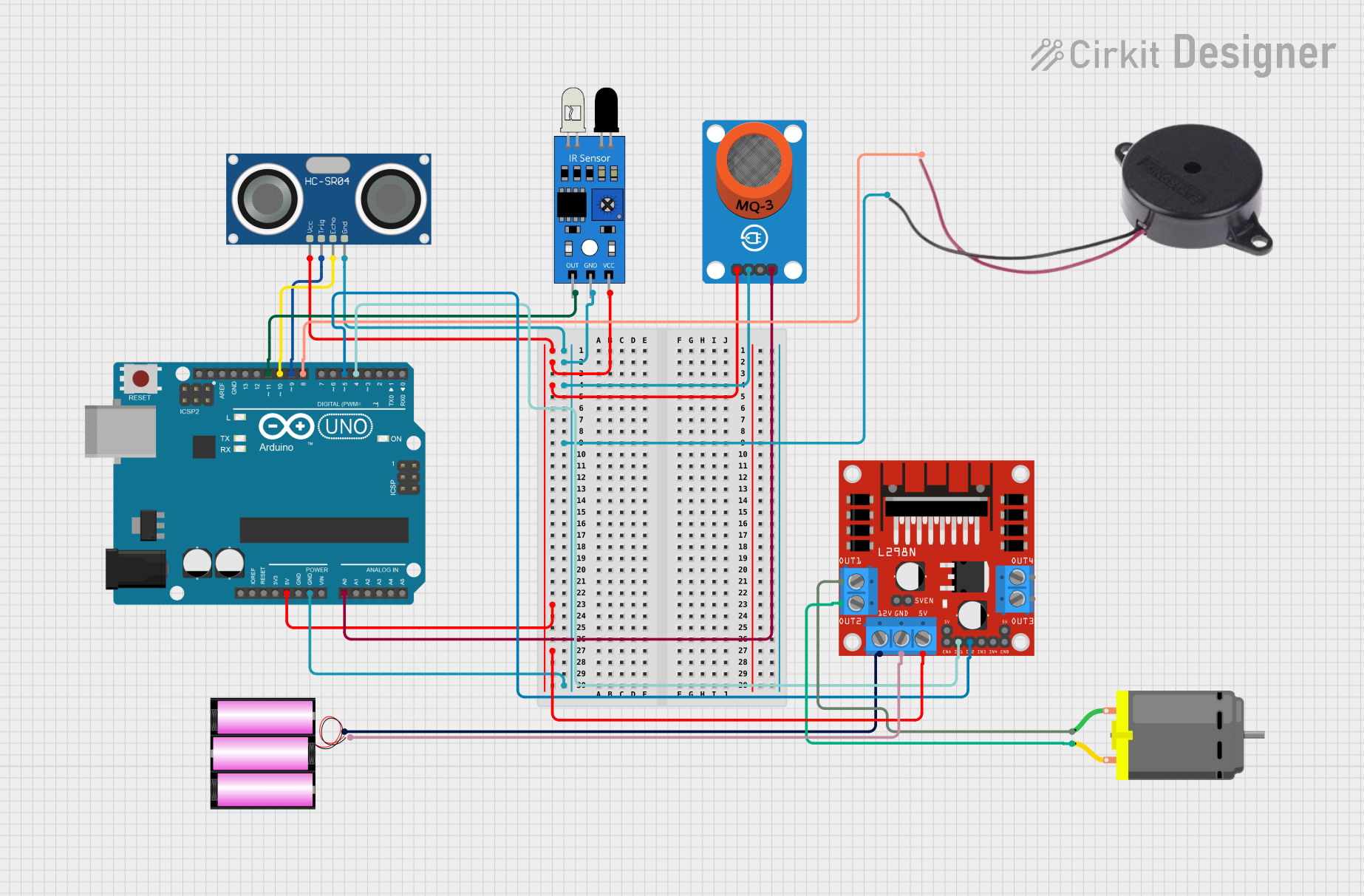
This circuit integrates various components including an Arduino UNO, sensors (IR, ultrasonic, and MQ-3 gas), a DC motor with its driver (L298N), a buzzer, and a 12V battery. The Arduino UNO serves as the central processing unit, interfacing with the sensors to receive environmental inputs and controlling the DC motor and buzzer based on these inputs. The L298N motor driver is used to control the direction and speed of the DC motor. The 12V battery provides the necessary power for the motor driver and, through voltage regulation, also powers the other components in the circuit.
Component List
Arduino UNO
- Microcontroller board based on the ATmega328P
- It has 14 digital input/output pins, 6 analog inputs, a 16 MHz quartz crystal, a USB connection, a power jack, an ICSP header, and a reset button.
IR Sensor
- An infrared sensor capable of detecting obstacles and measuring distances.
DC Motor
- An electric motor that runs on direct current (DC) electricity.
L298N DC Motor Driver
- A dual H-bridge motor driver that can drive two DC motors or one bipolar stepper motor.
HC-SR04 Ultrasonic Sensor
- An ultrasonic ranging module that provides 2cm to 400cm non-contact measurement functionality.
MQ-3 Alcohol Sensor
- A gas sensor used for alcohol detection.
Buzzer
- An electronic component that produces sound.
12V Battery
- A power source for the motor driver and indirectly for other components through voltage regulation.
Wiring Details
Arduino UNO
- 5V pin connected to the 5V power rail supplying power to other components.
- GND pin connected to the ground rail for common ground with other components.
- A0 pin connected to the MQ-3 sensor's analog output.
- D11 pin connected to the IR sensor's output.
- D10 pin connected to the HC-SR04 ultrasonic sensor's ECHO pin.
- D9 pin connected to the HC-SR04 ultrasonic sensor's TRIG pin.
- D8 pin connected to the Buzzer's positive terminal.
- D5 pin connected to the L298N motor driver's IN2 input.
- D4 pin connected to the L298N motor driver's IN1 input.
IR Sensor
- VCC pin connected to the 5V power rail.
- GND pin connected to the ground rail.
- OUT pin connected to the Arduino's D11 pin.
DC Motor
- Pin 1 connected to the L298N motor driver's OUT1 output.
- Pin 2 connected to the L298N motor driver's OUT2 output.
L298N DC Motor Driver
- 12V pin connected to the 12V battery's positive terminal.
- GND pin connected to the 12V battery's negative terminal.
- 5V pin connected to the 5V power rail.
- OUT1 and OUT2 connected to the DC motor.
- IN1 and IN2 connected to the Arduino's D4 and D5 pins respectively.
HC-SR04 Ultrasonic Sensor
- VCC pin connected to the 5V power rail.
- TRIG pin connected to the Arduino's D9 pin.
- ECHO pin connected to the Arduino's D10 pin.
- GND pin connected to the ground rail.
MQ-3 Alcohol Sensor
- VCC pin connected to the 5V power rail.
- GND pin connected to the ground rail.
- AO pin connected to the Arduino's A0 pin.
Buzzer
- POSITIVE terminal connected to the Arduino's D8 pin.
- NEGATIVE terminal connected to the ground rail.
12V Battery
- Positive terminal connected to the L298N motor driver's 12V input.
- Negative terminal connected to the L298N motor driver's GND input.
Documented Code
void setup() {
  // put your setup code here, to run once:

}

void loop() {
  // put your main code here, to run repeatedly:

}
The provided code is a template for the Arduino UNO microcontroller. The setup() function is called once when the program starts and is used to initialize settings. The loop() function is called repeatedly and contains the main logic of the program. The actual implementation details need to be filled in based on the specific requirements of the circuit's operation.