
ESP8266 and HC-05 Bluetooth-Based Home Automation System with 4-Channel Relay Control
View and Edit Project In Cirkit Designer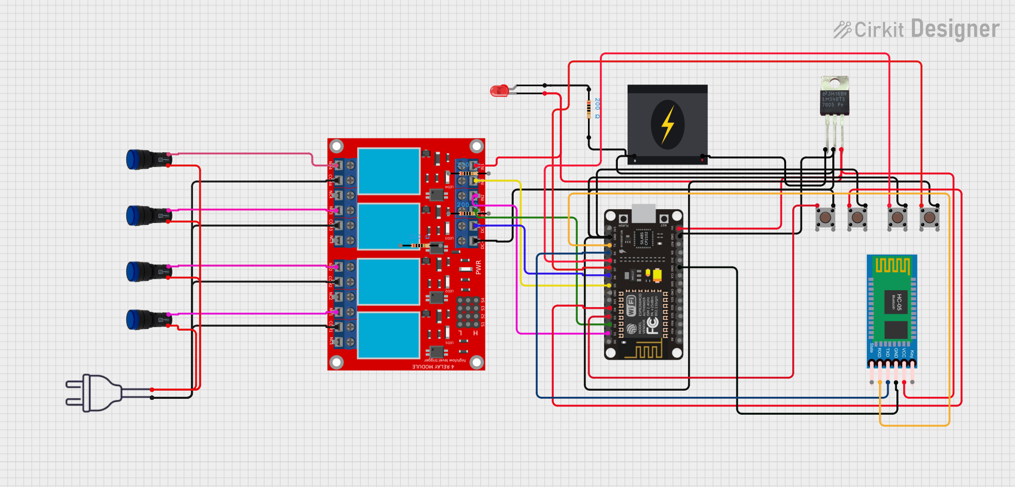
Circuit Documentation
Summary
This circuit is a Bluetooth-based Home Automation System that allows control of a 4-channel relay module using an ESP8266 NodeMCU and an HC-05 Bluetooth module. The relays can be controlled via Bluetooth commands or by pressing the connected pushbuttons. The system also includes pilot lamps to indicate the status of the relays.
Component List
4 Channel Relay Module
- Description: A module with four relays that can be controlled individually.
- Pins: N.O. 4, COM 4, N.C. 4, N.O. 3, COM 3, N.C. 3, N.O. 2, COM 2, N.C. 2, N.O. 1, COM 1, N.C. 1, Pin 13, Pin 14, Pin 15, Pin 16, Pin 17, Pin 18, Pin 19, Pin 20, Pin 21, Pin 22, Pin 23, Pin 24, VCC+, VCC- (GND), IN 1, IN 2, IN 3, IN 4
ESP8266 NodeMCU
- Description: A microcontroller with built-in Wi-Fi capabilities.
- Pins: D0, D1, D2, D3, D4, 3V3, GND, D5, D6, D7, D8, RX, TX, A0, RSV, SD3, SD2, SD1, CMD, SD0, CLK, EN, RST, VIN
Pushbutton
- Description: A simple pushbutton switch.
- Pins: Pin 3 (out), Pin 4 (out), Pin 1 (in), Pin 2 (in)
Pilot Lamp Blue
- Description: A blue pilot lamp used for indication.
- Pins: x1, x2
HC-05 Bluetooth Module
- Description: A Bluetooth module for wireless communication.
- Pins: Key, VCC, TXD, RXD, State, GND
Power 220V
- Description: A 220V power source.
- Pins: hot wire, neutral wire
240V Power Source
- Description: A 240V power source.
- Pins: Live, Neutral
Resistor
- Description: A resistor with a resistance of 200 Ohms.
- Pins: pin1, pin2
LED: Two Pin (Red)
- Description: A red LED.
- Pins: cathode, anode
LM340T5 7805
- Description: A voltage regulator.
- Pins: Vout, Vin, GND
Wiring Details
4 Channel Relay Module
- N.O. 4 is connected to x2 of Pilot Lamp Blue.
- COM 4, COM 1, COM 3, and COM 2 are connected to hot wire of Power 220V.
- N.O. 3 is connected to x2 of Pilot Lamp Blue.
- N.O. 2 is connected to x2 of Pilot Lamp Blue.
- N.O. 1 is connected to x2 of Pilot Lamp Blue.
- VCC+ is connected to pin2 of Resistor and Neutral of 240V Power Source.
- VCC- (GND) is connected to D6 of ESP8266 NodeMCU.
- IN 1 is connected to D2 of ESP8266 NodeMCU.
- IN 2 is connected to D1 of ESP8266 NodeMCU.
- IN 3 is connected to D5 of ESP8266 NodeMCU.
- IN 4 is connected to cathode of LED: Two Pin (Red).
ESP8266 NodeMCU
- GND is connected to pin2 of Resistor, GND of LM340T5 7805, and GND of HC-05 Bluetooth Module.
- VIN is connected to VCC of HC-05 Bluetooth Module and Vout of LM340T5 7805.
- RX is connected to TXD of HC-05 Bluetooth Module.
- TX is connected to RXD of HC-05 Bluetooth Module.
- D3 is connected to Pin 1 (in) of Pushbutton.
- D4 is connected to Pin 1 (in) of Pushbutton.
- D7 is connected to Pin 1 (in) of Pushbutton.
- D8 is connected to Pin 1 (in) of Pushbutton.
Pushbutton
- Pin 1 (in) of each pushbutton is connected to D3, D4, D7, and D8 of ESP8266 NodeMCU respectively.
- Pin 3 (out) of all pushbuttons are interconnected and connected to GND of ESP8266 NodeMCU.
Pilot Lamp Blue
- x2 of each pilot lamp is connected to N.O. 1, N.O. 2, N.O. 3, and N.O. 4 of 4 Channel Relay Module respectively.
- x1 of each pilot lamp is interconnected and connected to neutral wire of Power 220V.
HC-05 Bluetooth Module
- VCC is connected to VIN of ESP8266 NodeMCU.
- TXD is connected to RX of ESP8266 NodeMCU.
- RXD is connected to TX of ESP8266 NodeMCU.
- GND is connected to GND of ESP8266 NodeMCU.
Power 220V
- hot wire is connected to COM 4, COM 1, COM 3, and COM 2 of 4 Channel Relay Module.
- neutral wire is connected to x1 of each Pilot Lamp Blue.
240V Power Source
- Live is connected to Vin of LM340T5 7805.
- Neutral is connected to VCC+ of 4 Channel Relay Module and pin2 of Resistor.
Resistor
- pin1 is connected to anode of LED: Two Pin (Red).
- pin2 is connected to VCC+ of 4 Channel Relay Module, Neutral of 240V Power Source, and GND of ESP8266 NodeMCU.
LED: Two Pin (Red)
- cathode is connected to IN 4 of 4 Channel Relay Module.
- anode is connected to pin1 of Resistor.
LM340T5 7805
- Vin is connected to Live of 240V Power Source.
- Vout is connected to VIN of ESP8266 NodeMCU and VCC of HC-05 Bluetooth Module.
- GND is connected to GND of ESP8266 NodeMCU and pin2 of Resistor.
Code Documentation
/*
 * Bluetooth-based Home Automation System
 * This code allows control of a 4-channel relay module using an ESP8266 NodeMCU
 * and an HC-05 Bluetooth module. The relays can be controlled via Bluetooth
 * commands or by pressing the connected pushbuttons.
 */

#include <SoftwareSerial.h>

// Pin definitions
#define RELAY1_PIN D2
#define RELAY2_PIN D1
#define RELAY3_PIN D5
#define RELAY4_PIN D6
#define BUTTON1_PIN D3
#define BUTTON2_PIN D4
#define BUTTON3_PIN D7
#define BUTTON4_PIN D8

// Bluetooth module pins
#define BT_RX_PIN RX
#define BT_TX_PIN TX

SoftwareSerial BTSerial(BT_RX_PIN, BT_TX_PIN); // RX, TX

void setup() {
  // Initialize serial communication
  Serial.begin(9600);
  BTSerial.begin(9600);

  // Initialize relay pins as outputs
  pinMode(RELAY1_PIN, OUTPUT);
  pinMode(RELAY2_PIN, OUTPUT);
  pinMode(RELAY3_PIN, OUTPUT);
  pinMode(RELAY4_PIN, OUTPUT);

  // Initialize button pins as inputs
  pinMode(BUTTON1_PIN, INPUT);
  pinMode(BUTTON2_PIN, INPUT);
  pinMode(BUTTON3_PIN, INPUT);
  pinMode(BUTTON4_PIN, INPUT);

  // Turn off all relays initially