Cirkit Designer
Your all-in-one circuit design IDE
Home /
Project Documentation
Arduino UNO-Based Sensor Monitoring and Communication System
Circuit Documentation
Summary
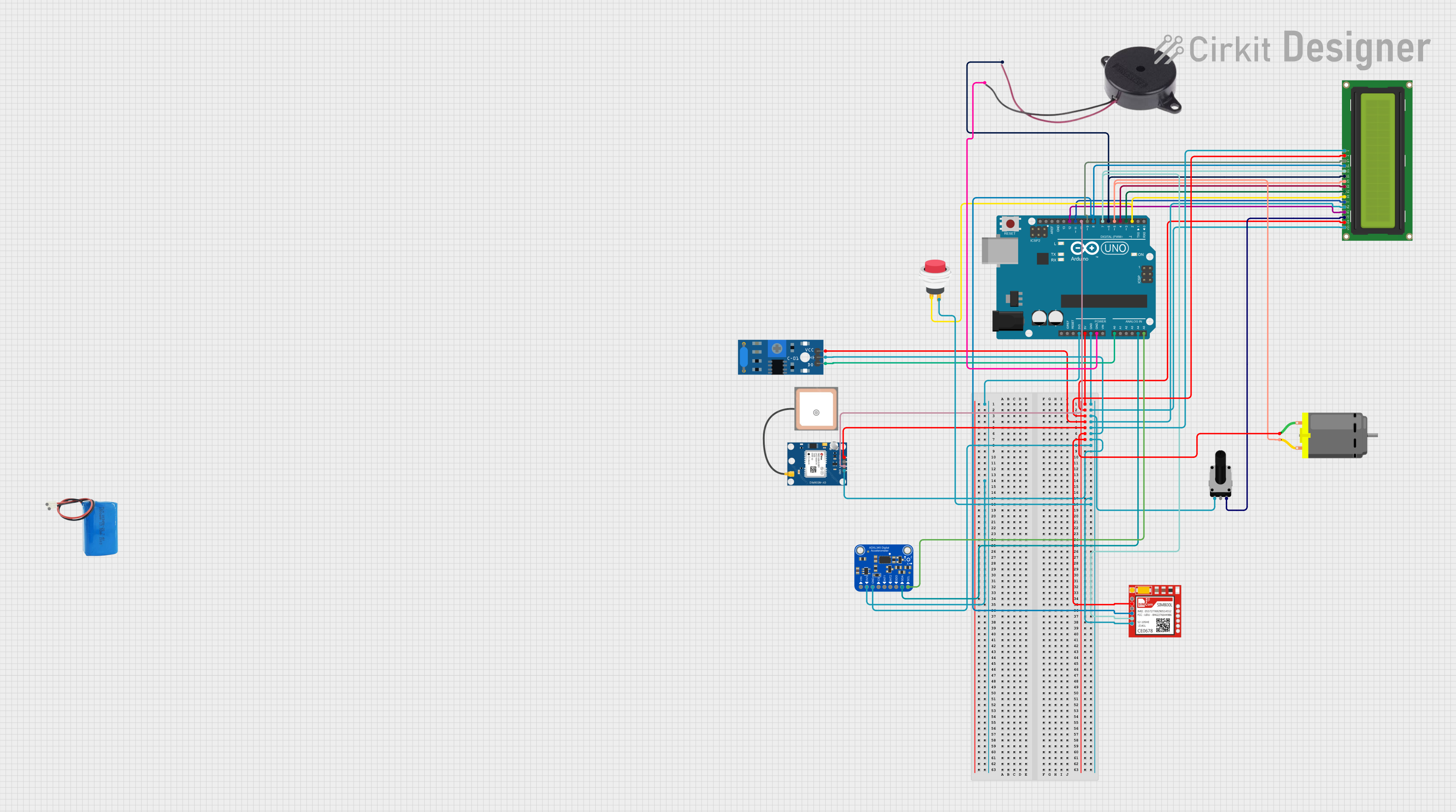
This document provides a detailed overview of a circuit designed to interface various components with an Arduino UNO microcontroller. The circuit includes sensors, a display, a motor, a GPS module, a GSM module, and a buzzer, all powered by a 5V supply. The Arduino UNO serves as the central processing unit, managing inputs from the sensors and controlling outputs to the display, motor, and buzzer. Communication with the GPS and GSM modules is also handled by the Arduino.
Component List
SW-420 Vibration Sensor
- Pins: vcc, Ground, Digital output
- Description: A sensor that detects vibrations and outputs a digital signal.
2Pin Push Switch
- Pins: Input +, Output +
- Description: A simple push-button switch that closes the circuit when pressed.
Buzzer
- Pins: POSITIVE, NEGATIVE
- Description: An electromechanical component that emits sound when energized.
5v Battery
- Pins: positive, negative
- Description: A power source providing a 5V supply to the circuit.
DC Motor
- Pins: pin 1, pin 2
- Description: An electric motor powered by DC voltage.
GPS NEO 6M
- Pins: VCC, RX, TX, GND
- Description: A GPS module for receiving location data.
Arduino UNO
- Pins: UNUSED, IOREF, Reset, 3.3V, 5V, GND, Vin, A0-A5, SCL, SDA, AREF, D0-D13
- Description: A microcontroller board based on the ATmega328P.
Rotary Potentiometer
- Pins: leg1, wiper, leg2
- Description: A variable resistor with a 10k Ohm resistance.
LCD Display 16x2
- Pins: LEDK, LEDA, DB0-DB7, E, RW, RS, VO, VDD, VSS
- Description: A liquid crystal display capable of displaying two lines of 16 characters each.
Adafruit ADXL345
- Pins: VIN, 3.3V, GND, CS, INT1, INT2, SDO/ADDR, SDA/SDIO, SCL
- Description: A digital accelerometer providing high-resolution measurements.
Sim800l
- Pins: NET, RST, VCC, RXD, TXD, GND
- Description: A GSM/GPRS module for cellular communication.
Wiring Details
SW-420 Vibration Sensor
- vcc: Connected to Arduino UNO 5V
- Ground: Connected to Arduino UNO GND
- Digital output: Connected to Arduino UNO A0
2Pin Push Switch
- Input +: Connected to Arduino UNO D2
- Output +: Connected to Arduino UNO GND
Buzzer
- POSITIVE: Connected to Arduino UNO D6
- NEGATIVE: Connected to Arduino UNO GND
DC Motor
- pin 1: Connected to Arduino UNO 5V
- pin 2: Connected to Arduino UNO D5
GPS NEO 6M
- VCC: Connected to Arduino UNO 5V
- RX: Not connected
- TX: Connected to Arduino UNO D10
- GND: Connected to Arduino UNO GND
Rotary Potentiometer
- leg1: Connected to Arduino UNO GND
- wiper: Not connected
- leg2: Connected to LCD Display 16x2 VO
LCD Display 16x2
- LEDK: Connected to Arduino UNO GND
- LEDA: Connected to Arduino UNO 5V
- DB0-DB7: Connected to Arduino UNO D0-D7 respectively
- E: Connected to Arduino UNO D11
- RW: Connected to Arduino UNO GND
- RS: Connected to Arduino UNO D12
- VO: Connected to Rotary Potentiometer leg2
- VDD: Connected to Arduino UNO 5V
- VSS: Connected to Arduino UNO GND
Adafruit ADXL345
- VIN: Not connected
- 3.3V: Connected to Arduino UNO 3.3V
- GND: Connected to Arduino UNO GND
- CS: Not connected
- INT1: Not connected
- INT2: Not connected
- SDO/ADDR: Not connected
- SDA/SDIO: Connected to Arduino UNO A4
- SCL: Connected to Arduino UNO A5
Sim800l
- NET: Not connected
- RST: Not connected
- VCC: Connected to Arduino UNO 5V
- RXD: Connected to Arduino UNO D8
- TXD: Connected to Arduino UNO D7
- GND: Connected to Arduino UNO GND
Documented Code
Arduino UNO Code (sketch.ino)
void setup() {
  // put your setup code here, to run once:

}

void loop() {
  // put your main code here, to run repeatedly:

}
Additional Notes
- The provided code is a template and does not contain any functional implementation. It needs to be populated with the logic to control and interact with the connected components based on the requirements of the circuit's application.
- The
setup()function is used to initialize variables, pin modes, start using libraries, etc. The code inside it runs once when the program starts. - The
loop()function is used for the main program logic. It runs repeatedly aftersetup()finishes. - The code for the Arduino UNO is minimal and serves as a starting point for further development.