
Circuit Documentation
Summary of the Circuit
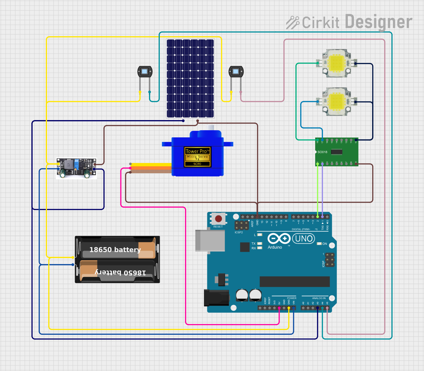
This circuit appears to be a solar-powered system with energy storage and control capabilities. It includes a solar panel for energy harvesting, a charge controller for battery management, a battery case for energy storage, and an Arduino UNO microcontroller for system control. The circuit also features a Darlington Driver to control power LEDs, a servomotor for actuation, and photodiodes for light sensing.
Component List
Photodiode
- Description: A semiconductor device that converts light into an electrical current. It is sensitive to light and can be used for light detection.
- Pins: cathode, anode
Power LED 12V 10W 0.8-0.9A
- Description: A high-power light-emitting diode designed to operate at 12V and consume between 0.8 to 0.9A of current.
- Pins: +, -
Solar Panel
- Description: A device that converts sunlight into electrical energy, providing a renewable source of power for the circuit.
- Pins: +, -
Charge Controller
- Description: A device used to regulate the voltage and current coming from the solar panel to the battery, ensuring the battery is charged efficiently and safely.
- Pins: GND, BAT, Vin
Arduino UNO
- Description: A microcontroller board based on the ATmega328P, widely used for building digital devices and interactive objects that can sense and control objects in the physical world.
- Pins: UNUSED, IOREF, Reset, 3.3V, 5V, GND, Vin, A0-A5, SCL, SDA, AREF, D0-D13
Darlington Driver
- Description: An integrated circuit that provides high-current gain and can drive heavy loads such as LEDs and motors.
- Pins: 1-18 (odd pins are inputs, even pins are outputs)
My Battery Case
- Description: A container for holding batteries, providing power storage for the circuit.
- Pins: +, -
Servomotor SG90
- Description: A small and lightweight servo motor capable of precise control; commonly used for steering mechanisms in small remote-controlled vehicles and aircraft.
- Pins: SIG, VCC, GND
Wiring Details
Photodiode
- Cathode: Connected to GND
- Anode: Connected to Arduino UNO analog pins (A4, A5)
Power LED 12V 10W 0.8-0.9A
- + (Positive): Connected to Darlington Driver outputs (pins 17, 18)
- - (Negative): Common ground with Darlington Driver pin 10
Solar Panel
- + (Positive): Connected to Charge Controller Vin and Arduino UNO A3
- - (Negative): Common ground with Servomotor SG90, Arduino UNO, Charge Controller, and Darlington Driver
Charge Controller
- GND: Common ground with other components
- BAT: Connected to My Battery Case +
- Vin: Connected to Solar Panel +
Arduino UNO
- Vin: Connected to My Battery Case +
- GND: Common ground with other components
- 5V: Connected to Servomotor SG90 VCC
- A3: Connected to Solar Panel +
- A4, A5: Connected to Photodiode anodes
- D1, D2: Connected to Darlington Driver inputs (pins 1, 2)
Darlington Driver
- Inputs (pins 1, 2): Connected to Arduino UNO digital pins (D1, D2)
- Outputs (pins 17, 18): Connected to Power LEDs +
- Pin 9: Common ground
- Pin 10: Common ground with Power LEDs -
My Battery Case
- + (Positive): Connected to Arduino UNO Vin and Charge Controller BAT
- - (Negative): Common ground with Photodiode cathode
Servomotor SG90
- SIG: Signal control from Arduino UNO (not specified in net list)
- VCC: Connected to Arduino UNO 5V
- GND: Common ground with other components
Documented Code
Arduino UNO Code (sketch.ino)
void setup() {
  // put your setup code here, to run once:

}

void loop() {
  // put your main code here, to run repeatedly:

}
Note: The provided code is a template and does not include specific functionality. It needs to be populated with the logic to control the circuit components based on the requirements of the project.