
ESP32-Based Wi-Fi Controlled 24V Input/Output Interface Module
View and Edit Project In Cirkit Designer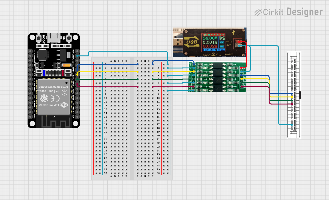
Circuit Documentation
Summary
This document provides a detailed overview of a circuit that includes a 24V power supply unit (PSU), a 40-pin connector, an ESP32 microcontroller, and a 3.3V PNP to 24V NPN photoelectric isolation module. The circuit is designed to interface various input and output signals through the ESP32 microcontroller and the isolation module, with power supplied by the 24V PSU.
Component List
24V PSU
- Description: Power supply unit providing 24V DC.
- Pins:
- 24V +
- 0V
40 Pin Connector
- Description: Connector with multiple general-purpose input and output pins.
- Pins:
- 0V for output pins 5D-20D
- Com for input pins 5c-20C
- No Connection (NC)
- GP In 0 to GP In 15
- GP Out 0 to GP Out 15
- 24V for output pins 5D-20D
ESP32 (30 pin)
- Description: ESP32 microcontroller with 30 pins.
- Pins:
- EN
- VP
- VN
- D34
- D35
- D32
- D33
- D25
- D26
- D27
- D14
- D12
- D13
- GND
- Vin
- D23
- D22
- TX0
- RX0
- D21
- D19
- D18
- D5
- TX2
- RX2
- D4
- D2
- D15
- 3V3
3.3V PNP to 24V NPN Photoelectric Iso Module
- Description: Isolation module converting 3.3V PNP signals to 24V NPN signals.
- Pins:
- In 01+
- In 01-
- In 02+
- In 02-
- In 03+
- In 03-
- In 04+
- In 04-
- 24V+
- 0V
- Out 01
- Out 02
- Out 03
- Out 04
Wiring Details
24V PSU
- 24V + is connected to 24V+ of the 3.3V PNP to 24V NPN Photoelectric Iso Module.
- 0V is connected to:
- Com for input pins 5c-20C of the 40 Pin Connector.
- 0V of the 3.3V PNP to 24V NPN Photoelectric Iso Module.
40 Pin Connector
- GP In 9 is connected to Out 01 of the 3.3V PNP to 24V NPN Photoelectric Iso Module.
- GP In 10 is connected to Out 02 of the 3.3V PNP to 24V NPN Photoelectric Iso Module.
- GP In 11 is connected to Out 03 of the 3.3V PNP to 24V NPN Photoelectric Iso Module.
- GP In 12 is connected to Out 04 of the 3.3V PNP to 24V NPN Photoelectric Iso Module.
ESP32 (30 pin)
- D14 is connected to In 01+ of the 3.3V PNP to 24V NPN Photoelectric Iso Module.
- GND is connected to:
- In 01- of the 3.3V PNP to 24V NPN Photoelectric Iso Module.
- In 02- of the 3.3V PNP to 24V NPN Photoelectric Iso Module.
- In 03- of the 3.3V PNP to 24V NPN Photoelectric Iso Module.
- In 04- of the 3.3V PNP to 24V NPN Photoelectric Iso Module.
- D27 is connected to In 02+ of the 3.3V PNP to 24V NPN Photoelectric Iso Module.
- D26 is connected to In 03+ of the 3.3V PNP to 24V NPN Photoelectric Iso Module.
- D25 is connected to In 04+ of the 3.3V PNP to 24V NPN Photoelectric Iso Module.
3.3V PNP to 24V NPN Photoelectric Iso Module
- 24V+ is connected to 24V + of the 24V PSU.
- 0V is connected to 0V of the 24V PSU and Com for input pins 5c-20C of the 40 Pin Connector.
- Out 01 is connected to GP In 9 of the 40 Pin Connector.
- Out 02 is connected to GP In 10 of the 40 Pin Connector.
- Out 03 is connected to GP In 11 of the 40 Pin Connector.
- Out 04 is connected to GP In 12 of the 40 Pin Connector.
- In 01+ is connected to D14 of the ESP32.
- In 01- is connected to GND of the ESP32.
- In 02+ is connected to D27 of the ESP32.
- In 02- is connected to GND of the ESP32.
- In 03+ is connected to D26 of the ESP32.
- In 03- is connected to GND of the ESP32.
- In 04+ is connected to D25 of the ESP32.
- In 04- is connected to GND of the ESP32.
Code
No code is provided for the microcontrollers in this circuit.