ESP8266 NodeMCU Controlled Smart Lighting with Motion Detection and Ambient Light Sensing
Circuit Documentation
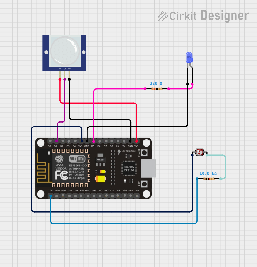
Summary
The circuit in question is designed to interface an ESP8266 NodeMCU microcontroller with a set of sensors and actuators to create a smart lighting system. The system uses a PIR motion sensor to detect movement and a photocell (LDR) to measure ambient light levels. Depending on these inputs, a blue LED is controlled to illuminate an area when motion is detected in low light conditions. The ESP8266 NodeMCU is also programmed to connect to a WiFi network and send sensor data to a specified server API.
Component List
Resistor (220 Ohms)
- Description: A resistor with a resistance of 220 Ohms.
- Purpose: Limits current to the blue LED to prevent damage.
Resistor (10k Ohms)
- Description: A resistor with a resistance of 10k Ohms.
- Purpose: Acts as part of a voltage divider with the photocell (LDR) to measure light levels.
ESP8266 NodeMCU
- Description: A microcontroller board with WiFi capabilities.
- Purpose: Acts as the central processing unit of the circuit, reads sensor data, controls the LED, and communicates with a server API over WiFi.
PIR Motion Sensor (Wokwi Compatible)
- Description: A passive infrared sensor that detects motion.
- Purpose: Provides input to the microcontroller to detect the presence of movement.
Photocell (LDR)
- Description: A light-dependent resistor that changes resistance with light levels.
- Purpose: Provides input to the microcontroller to measure ambient light levels.
LED: Two Pin (blue)
- Description: A blue light-emitting diode.
- Purpose: Acts as an indicator or light source that is controlled based on sensor inputs.
Wiring Details
Resistor (220 Ohms)
- Pin 1: Connected to ESP8266 NodeMCU pin D5.
- Pin 2: Connected to the anode of the blue LED.
Resistor (10k Ohms)
- Pin 1: Connected to ESP8266 NodeMCU pin A0.
- Pin 2: Connected to pin 1 of the photocell (LDR).
ESP8266 NodeMCU
- D5: Connected to pin 1 of the 220 Ohm resistor.
- A0: Connected to pin 1 of the 10k Ohm resistor.
- D1: Connected to the OUT pin of the PIR motion sensor.
- 3V3: Connected to the VCC pin of the PIR motion sensor and pin 0 of the photocell (LDR).
- GND: Connected to the cathode of the blue LED and the GND pin of the PIR motion sensor.
PIR Motion Sensor (Wokwi Compatible)
- VCC: Connected to ESP8266 NodeMCU pin 3V3.
- OUT: Connected to ESP8266 NodeMCU pin D1.
- GND: Connected to ESP8266 NodeMCU pin GND.
Photocell (LDR)
- Pin 0: Connected to ESP8266 NodeMCU pin 3V3.
- Pin 1: Connected to pin 2 of the 10k Ohm resistor.
LED: Two Pin (blue)
- Anode: Connected to pin 2 of the 220 Ohm resistor.
- Cathode: Connected to ESP8266 NodeMCU pin GND.
Documented Code
#include <ESP8266WiFi.h>
#include <ESP8266HTTPClient.h>
#include <WiFiClient.h>

int ldrPin = A0;      // Pin LDR
int pirPin = D5;      // Pin PIR sensor
int ledPin = D2;      // Pin untuk LED

int ldrThreshold = 5;  // Kalibrasi ambang batas terang
int pirState = LOW;    // Status PIR (LOW = tidak ada gerakan, HIGH = ada gerakan)
unsigned long pirLastTriggered = 0;  // Waktu terakhir PIR mendeteksi gerakan
unsigned long pirDelay = 2500;  // Delay 2.5 detik untuk PIR

const char* ssid = "cm@wifi.id";          // Ganti dengan SSID Wi-Fi
const char* password = "Admin#123";  // Ganti dengan password Wi-Fi
const char* serverName = "http://192.168.100.4/IOT_API/api.php"; // Ganti dengan alamat server API lokal

WiFiClient client;
int lastLedStatus = LOW; // Variabel untuk menyimpan status LED sebelumnya

void setup() {
    pinMode(ledPin, OUTPUT);  // Mengatur pin LED sebagai output
    pinMode(pirPin, INPUT);   // Mengatur pin PIR sebagai input
    Serial.begin(115200);     // Memulai komunikasi serial dengan baud rate 115200

    // Menghubungkan ke WiFi
    WiFi.begin(ssid, password);
    while (WiFi.status() != WL_CONNECTED) {
        delay(1000);
        Serial.println("Connecting to WiFi...");
    }
    Serial.println("Connected to WiFi");
}

void loop() {
    // Membaca nilai dari LDR
    int ldrValue = analogRead(ldrPin);
    Serial.print("LDR Value: ");
    Serial.println(ldrValue);

    // Membaca status dari PIR sensor
    pirState = digitalRead(pirPin);

    // Jika ruangan terang, matikan LED dan abaikan PIR
    if (ldrValue <= ldrThreshold) {  // Ruangan terang
        digitalWrite(ledPin, LOW);  // Matikan LED
        int currentLedStatus = LOW; // Status LED saat ini

        // Kirim data hanya jika ada perubahan
        if (currentLedStatus != lastLedStatus) {
            lastLedStatus = currentLedStatus; // Update status LED
            sendDataToAPI(ldrValue, pirState == HIGH ? 1 : 0, lastLedStatus); // Kirim data
        }

        Serial.println("Ruangan terang, LED mati");
    } else {
        // Jika ruangan gelap dan ada gerakan, nyalakan LED
        if (pirState == HIGH) {
            delay(100); // Debounce delay
            pirState = digitalRead(pirPin); // Baca lagi setelah delay
            if (pirState == HIGH) {
                pirLastTriggered = millis();  // Simpan waktu saat gerakan terdeteksi
                digitalWrite(ledPin, HIGH);   // Nyalakan LED
                int currentLedStatus = HIGH; // Status LED saat ini

                // Kirim data hanya jika ada perubahan
                if (currentLedStatus != lastLedStatus) {
                    lastLedStatus = currentLedStatus; // Update status LED
                    sendDataToAPI(ldrValue, 1, lastLedStatus); // Kirim data
                }

                Serial.println("Ruangan gelap dan ada gerakan, LED nyala");
            }
        }

        // Jika tidak ada gerakan dalam waktu pirDelay, matikan LED
        if (millis() - pirLastTriggered >= pirDelay) {
            digitalWrite(ledPin, LOW);   // Matikan LED setelah pirDelay tanpa gerakan
            int currentLedStatus = LOW; // Status LED saat ini

            // Kirim data hanya jika ada perubahan
            if (currentLedStatus != lastLedStatus) {
                lastLedStatus = currentLedStatus; // Update status LED
                sendDataToAPI(ldrValue, 0, lastLedStatus); // Kirim data
            }

            Serial.println("Tidak ada gerakan, LED mati");
        }
    }

    delay(2000);  // Sensor readings setiap 2 detik
}

// Fungsi untuk mengirim data ke API
void sendDataToAPI(int ldrValue, int pirStatus, int ledStatus) {
    if (WiFi.status() == WL_CONNECTED) { // Cek apakah terhubung ke WiFi
        WiFiClient client;
        HTTPClient http;

        // Ubah serverName menjadi tipe String agar dapat digabungkan dengan string lain
        String serverPath = String(serverName) + "?ldr=" + String(ldrValue) + "&pir=" + String(pirStatus) + "&led=" + String(ledStatus);

        http.begin(client, serverPath.c_str());
        int httpResponseCode = http.GET();

        if (httpResponseCode > 0) {
            String payload = http.getString();
            Serial.println(httpResponseCode);
            Serial.println(payload);
        } else {
            Serial.print("Error code: ");
            Serial.println(httpResponseCode);
        }
        http.end(); // Bebaskan resource
    } else {
        Serial.println("WiFi Disconnected");
    }
}
Note: The code provided is for the ESP8266 NodeMCU microcontroller. It includes WiFi connectivity setup, sensor reading, LED control based on sensor input, and data transmission to a server API. The code is written in Arduino C/C++ and is intended to be compiled and uploaded to the microcontroller using the Arduino IDE or a similar development environment.