
Arduino Nano-Based Pulse Pattern Generator with DIP Switch Control and Potentiometer Adjustment
View and Edit Project In Cirkit Designer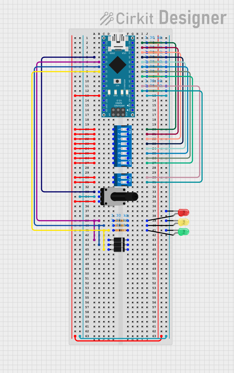
Circuit Documentation
Summary
This circuit is designed to control a set of LEDs and read input from DIP switches and a rotary potentiometer using an Arduino Nano. The Arduino Nano reads the state of the DIP switches to determine pulse patterns and uses the potentiometer to adjust the delay time between pulses. The circuit also includes resistors and diodes for current limiting and protection.
Component List
Arduino Nano
- Description: Microcontroller board based on the ATmega328P.
- Pins: D1/TX, D0/RX, RESET, GND, D2, D3, D4, D5, D6, D7, D8, D9, D10, D11/MOSI, D12/MISO, VIN, 5V, A7, A6, A5, A4, A3, A2, A1, A0, AREF, 3V3, D13/SCK
DIP Switch (8 Position)
- Description: 8-position DIP switch for selecting pulse patterns.
- Pins: 1, 2, 7, 8, 3, 4, 6, 5, 9, 10, 11, 12, 13, 14, 15, 16
DIP Switch (2 Position)
- Description: 2-position DIP switch for mode selection.
- Pins: 1, 2, 3, 4
LED: Two Pin (yellow)
- Description: Yellow LED.
- Pins: cathode, anode
LED: Two Pin (red)
- Description: Red LED.
- Pins: cathode, anode
LED: Two Pin (green)
- Description: Green LED.
- Pins: cathode, anode
Resistor (3300 Ohms)
- Description: Resistor with a resistance of 3300 Ohms.
- Pins: pin1, pin2
Rotary Potentiometer (10k Ohms)
- Description: Potentiometer with a resistance of 10k Ohms.
- Pins: leg1, wiper, leg2
Diode
- Description: General-purpose diode.
- Pins: cathode, anode
Wiring Details
Arduino Nano
D12/MISO connected to:
- Resistor (pin1)
- DIP Switch (8 Position) (pin 16)
D11/MOSI connected to:
- Resistor (pin1)
- DIP Switch (8 Position) (pin 15)
D10 connected to:
- Resistor (pin1)
- DIP Switch (8 Position) (pin 14)
A0 connected to:
- Rotary Potentiometer (leg1)
D9 connected to:
- Resistor (pin1)
- DIP Switch (8 Position) (pin 13)
A1 connected to:
- Resistor (pin1)
- Diode (anode)
D8 connected to:
- Resistor (pin1)
- DIP Switch (8 Position) (pin 12)
A2 connected to:
- Resistor (pin1)
- Diode (anode)
D7 connected to:
- Resistor (pin1)
- DIP Switch (8 Position) (pin 11)
A3 connected to:
- Resistor (pin1)
- Diode (anode)
D6 connected to:
- Resistor (pin1)
- DIP Switch (8 Position) (pin 10)
D5 connected to:
- Resistor (pin1)
- DIP Switch (8 Position) (pin 9)
D3 connected to:
- Resistor (pin1)
- DIP Switch (2 Position) (pin 4)
D2 connected to:
- Resistor (pin1)
- DIP Switch (2 Position) (pin 3)
5V connected to:
- DIP Switch (8 Position) (pins 1, 2, 3, 4, 5, 6, 7, 8)
- DIP Switch (2 Position) (pins 1, 2)
- Rotary Potentiometer (leg2)
GND connected to:
- LED: Two Pin (yellow) (cathode)
- LED: Two Pin (red) (cathode)
- LED: Two Pin (green) (cathode)
- Resistor (pin2)
- Rotary Potentiometer (wiper)
DIP Switch (8 Position)
Pin 16 connected to:
- Resistor (pin1)
- Arduino Nano (D12/MISO)
Pin 15 connected to:
- Resistor (pin1)
- Arduino Nano (D11/MOSI)
Pin 14 connected to:
- Resistor (pin1)
- Arduino Nano (D10)
Pin 13 connected to:
- Resistor (pin1)
- Arduino Nano (D9)
Pin 12 connected to:
- Resistor (pin1)
- Arduino Nano (D8)
Pin 11 connected to:
- Resistor (pin1)
- Arduino Nano (D7)
Pin 10 connected to:
- Resistor (pin1)
- Arduino Nano (D6)
Pin 9 connected to:
- Resistor (pin1)
- Arduino Nano (D5)
Pins 1, 2, 3, 4, 5, 6, 7, 8 connected to:
- Arduino Nano (5V)
DIP Switch (2 Position)
Pin 4 connected to:
- Resistor (pin1)
- Arduino Nano (D3)
Pin 3 connected to:
- Resistor (pin1)
- Arduino Nano (D2)
Pins 1, 2 connected to:
- Arduino Nano (5V)
LED: Two Pin (yellow)
Cathode connected to:
- Arduino Nano (GND)
Anode connected to:
- Resistor (pin2)
LED: Two Pin (red)
Cathode connected to:
- Arduino Nano (GND)
Anode connected to:
- Resistor (pin2)
LED: Two Pin (green)
Cathode connected to:
- Arduino Nano (GND)
Anode connected to:
- Resistor (pin2)
Resistors
Pin1 connected to:
- Various pins on the Arduino Nano and DIP switches as detailed above.
Pin2 connected to:
- Arduino Nano (GND)
Rotary Potentiometer
Leg1 connected to:
- Arduino Nano (A0)
Wiper connected to:
- Arduino Nano (GND)
Leg2 connected to:
- Arduino Nano (5V)
Diodes
Anode connected to:
- Resistor (pin1)
Cathode connected to:
- Not connected in the provided net list.
Code Documentation
// Beat selectors
const int P1 = 12;
const int P2 = 11;
const int P3 = 10;
const int P4 = 9;
const int P5 = 8;
const int P6 = 7;
const int P7 = 6;
const int P8 = 5;

// Mode select
const int INx0 = 2; // IN bit 0
const int IN0x = 3; // IN bit 1

// Output pins
const int Pulse01 = 15; // Pulse for mode 01
const int Pulse10 = 16; // Pulse for mode 10
const int Pulse11 = 17; // Pulse for mode 11

// Potentiometer pin
const int POT_PIN = A0;

// Variables
int delayTime;
int pulsePattern01 = 0;
int pulsePattern10 = 0;
int pulsePattern11 = 0;

// For tracking time for each pulse
unsigned long lastPulseTime01 = 0;
unsigned long lastPulseTime10 = 0;
unsigned long lastPulseTime11 = 0;
int currentStep01 = 0;
int currentStep10 = 0;
int currentStep11 = 0;

void setup() {
  // Initialize serial for debugging
  Serial.begin(9600);

  // Input pins
  pinMode(P1, INPUT);
  pinMode(P2, INPUT);
  pinMode(P3, INPUT);
  pinMode(P4, INPUT);
  pinMode(P5, INPUT);
  pinMode(P6, INPUT);
  pinMode(P7, INPUT);
  pinMode(P8, INPUT);
  pinMode(INx0, INPUT);
  pinMode(IN0x, INPUT