
Arduino-Controlled Relay Switch with LCD Feedback and Buzzer Notification
View and Edit Project In Cirkit Designer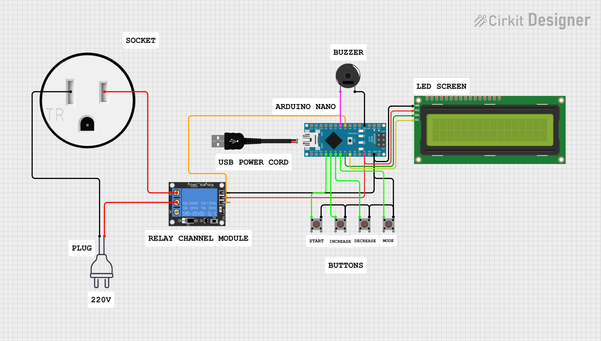
Circuit Documentation
Summary
This circuit incorporates a variety of components including an Arduino Nano microcontroller, a Piezo Buzzer, an I2C LCD 16x2 Screen, a 1-Channel Relay, a power supply, multiple pushbuttons, and a 120V Outlet. The Arduino Nano serves as the central processing unit, controlling the relay, buzzer, and LCD screen, as well as reading inputs from the pushbuttons. The relay is used to switch a 220V power source, which is connected to a 120V Outlet. The pushbuttons provide user input to the Arduino, which can then display information on the LCD screen or activate the buzzer.
Component List
- Arduino Nano: A compact microcontroller board based on the ATmega328P, featuring digital and analog I/O pins.
- Piezo Buzzer: An electronic device that emits sound when an electrical signal is applied.
- I2C LCD 16x2 Screen: A liquid crystal display capable of showing 16 characters per line, with 2 lines, using the I2C communication protocol.
- 1-Channel Relay (5V 10A): An electrically operated switch that allows you to control a high power circuit with a low power signal.
- Power 220V: A power supply component that provides 220V AC power.
- Pushbutton: A simple switch mechanism for controlling some aspect of a machine or a process.
- 120V Outlet: A standard electrical outlet for delivering AC power.
- USB male 2 pin connection: A USB connector with two pins for power connections.
Wiring Details
Arduino Nano
- GND: Connected to the ground of the Piezo Buzzer, ground of the I2C LCD Screen, ground of the 1-Channel Relay, and the ground (Pin 3 out) of all Pushbuttons.
- D5: Controls the signal pin of the 1-Channel Relay.
- D6: Connected to pin 1 of the Piezo Buzzer.
- 5V: Powers the VCC of the I2C LCD Screen and the power pin of the 1-Channel Relay.
- A5: Connected to the SCL pin of the I2C LCD Screen.
- A4: Connected to the SDA pin of the I2C LCD Screen.
- A3: Connected to Pin 1 (in) of the first Pushbutton.
- A2: Connected to Pin 1 (in) of the second Pushbutton.
- A1: Connected to Pin 1 (in) of the third Pushbutton.
- A0: Connected to Pin 1 (in) of the fourth Pushbutton.
Piezo Buzzer
- Pin 1: Connected to D6 on the Arduino Nano.
- Pin 2: Connected to GND on the Arduino Nano.
I2C LCD 16x2 Screen
- SCL: Connected to A5 on the Arduino Nano.
- SDA: Connected to A4 on the Arduino Nano.
- VCC (5V): Powered by the 5V output from the Arduino Nano.
- GND: Connected to GND on the Arduino Nano.
1-Channel Relay (5V 10A)
- Signal: Controlled by D5 on the Arduino Nano.
- Power: Powered by the 5V output from the Arduino Nano.
- Ground: Connected to GND on the Arduino Nano.
- C: Connected to the hot wire of the power 220V.
- NO: Connected to the AC Hot of the 120V Outlet.
Power 220V
- Hot wire: Connected to the C pin of the 1-Channel Relay.
- Neutral wire: Connected to the AC Neutral of the 120V Outlet.
Pushbuttons
- Pin 1 (in): Each connected to a separate analog input on the Arduino Nano (A0, A1, A2, A3).
- Pin 3 (out): All connected to GND on the Arduino Nano.
120V Outlet
- AC Neutral: Connected to the neutral wire of the power 220V.
- AC Hot: Connected to the NO pin of the 1-Channel Relay.
Documented Code
void setup() {
  // put your setup code here, to run once:

}

void loop() {
  // put your main code here, to run repeatedly:

}
The provided code is a template with empty setup() and loop() functions, which are the standard structure for Arduino sketches. The setup() function is intended to contain initialization code that runs once when the microcontroller is powered on or reset. The loop() function is for code that runs continuously, allowing the microcontroller to perform tasks, respond to inputs, and control outputs like the relay, buzzer, and LCD screen.