
Arduino UNO-Based RFID and Bluetooth Interactive Display with Stepper Motor Control
View and Edit Project In Cirkit Designer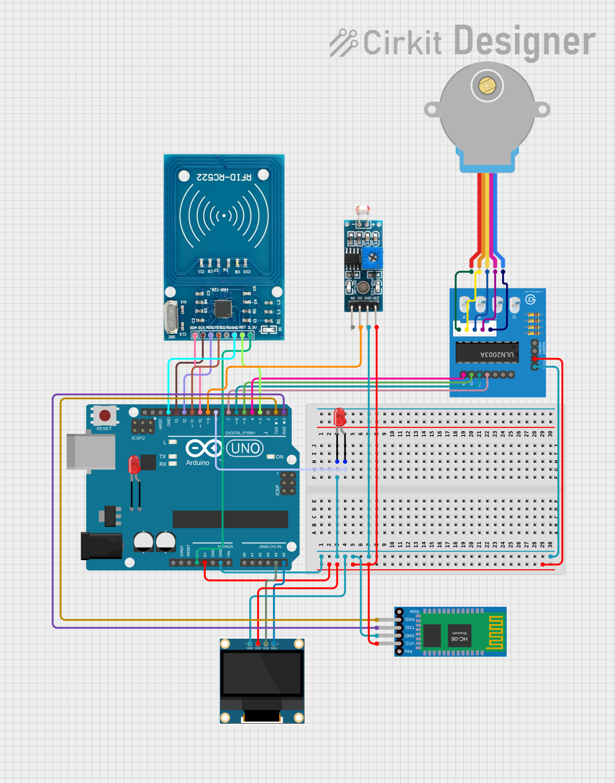
Circuit Documentation
Summary
This circuit integrates various components controlled by an Arduino UNO microcontroller to perform a range of functions. The circuit includes an OLED display for visual output, an RFID-RC522 module for RFID reading, a Module LDR for light detection, a stepper motor driven by a ULN2003A breakout board for motion control, LEDs for visual indication, and a Bluetooth HC-06 module for wireless communication. The Arduino UNO serves as the central processing unit, interfacing with each module and sensor to create an interactive system.
Component List
Arduino UNO
- Microcontroller board based on the ATmega328P
- It has 14 digital input/output pins, 6 analog inputs, a 16 MHz quartz crystal, a USB connection, a power jack, an ICSP header, and a reset button.
0.96" OLED
- A small display that uses the I2C communication protocol.
- It is typically used for displaying data, graphics, and text.
RFID-RC522
- An RFID reader/writer module that operates at 13.56 MHz.
- It is commonly used for contactless communication and identification.
Module LDR
- A light-dependent resistor module.
- It is used to detect the presence and intensity of light.
Adafruit Gear-Reduced Stepper Motor (small)
- A small stepper motor suitable for precise positioning and movement.
ULN2003A breakout board
- A driver board designed to drive stepper motors.
- It contains a ULN2003A transistor array.
LED: Two Pin (red)
- A basic red LED with an anode and cathode for simple indication purposes.
Bluetooth HC-06
- A Bluetooth module that allows for wireless communication with other Bluetooth-enabled devices.
Wiring Details
Arduino UNO
- GND: Connected to the ground pins of the OLED, Bluetooth HC-06, Module LDR, ULN2003A breakout board, and one of the red LEDs.
- 3.3V: Supplies power to the RFID-RC522.
- 5V: Powers the OLED, Module LDR, Bluetooth HC-06, and ULN2003A breakout board.
- A4 (SDA): Connected to the SCK pin of the OLED for I2C communication.
- A5 (SCL): Connected to the SDA pin of the OLED for I2C communication.
- D0-D13: Various digital pins connected to the RFID-RC522, Module LDR, ULN2003A breakout board, Bluetooth HC-06, and LEDs for control signals.
0.96" OLED
- GND: Connected to the ground (common ground with Arduino UNO).
- VDD: Powered by the 5V output from the Arduino UNO.
- SCK: Connected to A4 on the Arduino UNO for I2C communication.
- SDA: Connected to A5 on the Arduino UNO for I2C communication.
RFID-RC522
- VCC (3.3V): Powered by the 3.3V output from the Arduino UNO.
- RST: Connected to D3 on the Arduino UNO for reset control.
- GND: Connected to the ground (common ground with Arduino UNO).
- IRQ: Not connected in this circuit.
- MISO, MOSI, SCK, SDA: Connected to D11, D12, D13, and D10 respectively on the Arduino UNO for SPI communication.
Module LDR
- VCC: Powered by the 5V output from the Arduino UNO.
- GND: Connected to the ground (common ground with Arduino UNO).
- DO: Connected to D9 on the Arduino UNO for digital signal output.
- AO: Not connected in this circuit.
Adafruit Gear-Reduced Stepper Motor (small)
- RED, ORANGE, YELLOW, PINK, BLUE: Connected to the corresponding wires on the ULN2003A breakout board to control the stepper motor phases.
ULN2003A breakout board
- In 1, In 2, In 3, In 4: Connected to D4, D5, D6, and D7 on the Arduino UNO for control signals.
- 0V: Connected to the ground (common ground with Arduino UNO).
- +5V: Powered by the 5V output from the Arduino UNO.
- ON/OFF jumper switch: Not detailed in the connection list.
- BLUE, PINK, YELLOW, ORANGE, RED wire: Connected to the corresponding wires of the stepper motor.
LED: Two Pin (red)
- cathode: Connected to the ground (common ground with Arduino UNO).
- anode: Connected to D8 on the Arduino UNO for control.
Bluetooth HC-06
- VCC: Powered by the 5V output from the Arduino UNO.
- GND: Connected to the ground (common ground with Arduino UNO).
- TXD: Connected to D0 on the Arduino UNO for transmitting data.
- RXD: Connected to D1 on the Arduino UNO for receiving data.
Documented Code
Arduino UNO Code (sketch.ino)
void setup() {
  // put your setup code here, to run once:

}

void loop() {
  // put your main code here, to run repeatedly:

}
Note: The provided code is a template and does not include specific functionality. It needs to be populated with the setup and loop functions to control the connected components based on the desired application.