
Arduino-Controlled Robotic Vehicle with Ultrasonic Obstacle Avoidance and Light Sensing
View and Edit Project In Cirkit Designer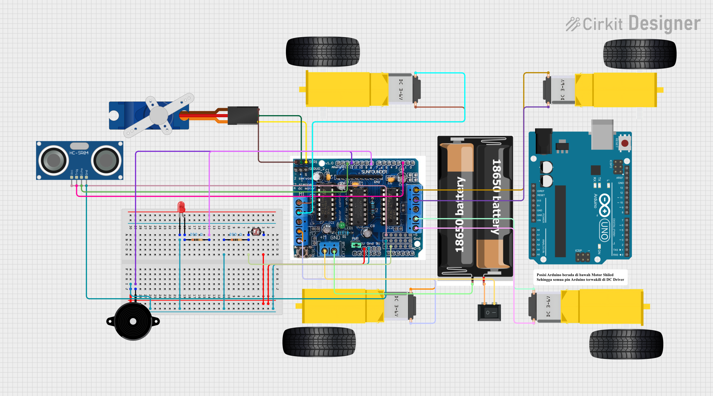
Circuit Documentation
Summary
This document provides a detailed overview of a circuit designed to interface with various components including an Arduino UNO, a Tower Pro SG90 servo, gearmotors, an HC-SR04 Ultrasonic Sensor, an L293D driver shield, a power source (2x 18650 batteries), a rocker switch, an LED, a piezo speaker, resistors, and a photocell (LDR). The circuit is designed to control motors, read sensor inputs, and provide visual and auditory feedback.
Component List
Arduino UNO
- Microcontroller board based on the ATmega328P
- Pins: UNUSED, IOREF, Reset, 3.3V, 5V, GND, Vin, A0-A5, SCL, SDA, AREF, D0-D13
Tower Pro SG90 Servo
- Small and lightweight servo motor
- Pins: Signal, +5V, GND
Gearmotor DC Wheels (Right and Left)
- DC motors with gear reduction used for driving wheels
- Pins: PIN1, PIN2
2x 18650 Batteries
- Power source for the circuit
- Pins: VCC, GND
HC-SR04 Ultrasonic Sensor
- Ultrasonic distance sensor
- Pins: VCC, TRIG, ECHO, GND
L293D Driver Shield
- Motor driver shield for controlling multiple motors
- Pins: 5V, GND, A0-A5, M+, M1-M4, 0-12, Aref, Servo1, Servo2, +, -, 9V
Rocker Switch (SPST)
- Single Pole Single Throw switch
- Pins: 1, 2
LED: Two Pin (Red)
- Red light-emitting diode
- Pins: Cathode, Anode
Piezo Speaker
- Electronic device that can produce sound
- Pins: Pin1, Pin2
Resistor
- Electrical component that limits or regulates the flow of electrical current
- Resistance: 200 Ohms
Photocell (LDR)
- Light-dependent resistor whose resistance changes with light intensity
- Pins: Pin 0, Pin 1
Wiring Details
Arduino UNO
- No direct wiring information provided.
Tower Pro SG90 Servo
- Signal connected to L293D Driver Shield (Servo1)
- +5V connected to L293D Driver Shield (+)
- GND connected to L293D Driver Shield (-)
Gearmotor DC Wheels (Right and Left)
- PIN1 and PIN2 of each motor connected to corresponding M1-M4 pins on L293D Driver Shield
2x 18650 Batteries
- VCC connected to Rocker Switch (Pin 1)
- GND connected to L293D Driver Shield (GND)
HC-SR04 Ultrasonic Sensor
- VCC connected to L293D Driver Shield (5V)
- TRIG connected to L293D Driver Shield (Pin 2)
- ECHO connected to L293D Driver Shield (Pin 12)
- GND connected to L293D Driver Shield (GND)
L293D Driver Shield
- 5V and GND used for power distribution
- A0-A5, M+, M1-M4, 0-12, Servo1, Servo2, +, -, 9V used for interfacing with other components
Rocker Switch (SPST)
- Pin 1 connected to 2x 18650 Batteries (VCC)
- Pin 2 connected to L293D Driver Shield (M+)
LED: Two Pin (Red)
- Cathode connected to L293D Driver Shield (GND) through a 200 Ohm resistor
- Anode connected to L293D Driver Shield (Pin 8)
Piezo Speaker
- Pin1 connected to L293D Driver Shield (Pin 12)
- Pin2 connected to L293D Driver Shield (GND) through a 200 Ohm resistor
Resistor (200 Ohms)
- One resistor connected between Photocell (LDR) Pin 0 and L293D Driver Shield (A1)
- Another resistor connected between LED Cathode and L293D Driver Shield (GND)
Photocell (LDR)
- Pin 1 connected to L293D Driver Shield (5V)
- Pin 0 connected to L293D Driver Shield (A1) through a 200 Ohm resistor
Documented Code
Arduino UNO Sketch (sketch.ino)
void setup() {
  // put your setup code here, to run once:

}

void loop() {
  // put your main code here, to run repeatedly:

}
Additional Notes
- The provided code is a template and does not contain any functional code specific to the circuit's operation.
- Further implementation is required to control the motors, read sensor inputs, and activate the LED and piezo speaker based on the circuit's logic.