
Arduino UNO Based Count-Up Timer with I2C LCD Display and Button Control
View and Edit Project In Cirkit Designer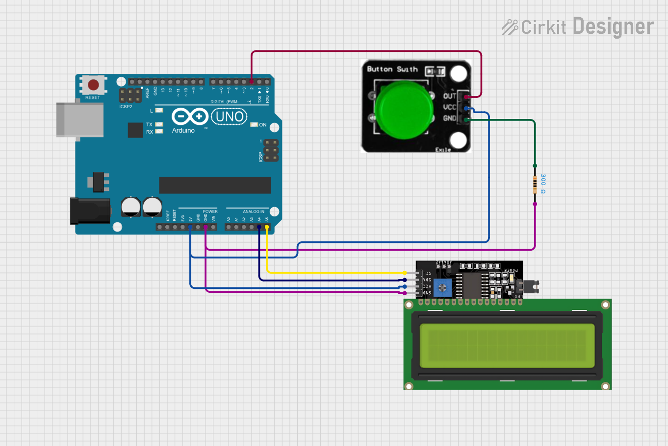
Circuit Documentation
Summary of the Circuit
This circuit is designed around an Arduino UNO microcontroller and includes an LCD Display (16x4 I2C) for output and a green button as an input device. The purpose of the circuit is to implement a count-up timer that starts counting when the green button is pressed and displays the elapsed time on the LCD display. The timer stops and resets when the button is pressed again. The LCD display communicates with the Arduino UNO via the I2C protocol, and the green button is connected to a digital input pin with a pull-down resistor to ensure a stable button state.
Component List
Arduino UNO
- Description: A microcontroller board based on the ATmega328P.
- Pins: UNUSED, IOREF, Reset, 3.3V, 5V, GND, Vin, A0-A5, SCL, SDA, AREF, D0-D13
LCD Display 16x4 I2C
- Description: A 16x4 character LCD display with an I2C interface.
- Pins: SCL, SDA, VCC, GND
Green Button
- Description: A momentary pushbutton switch.
- Pins: OUT, VCC, GND
Resistor
- Description: A passive two-terminal electrical component that implements electrical resistance.
- Resistance: 300 Ohms
- Pins: pin1, pin2
Wiring Details
Arduino UNO
- 5V: Connected to the VCC of the LCD Display and the VCC of the Green Button.
- GND: Connected to the GND of the LCD Display and one end of the Resistor.
- A4 (SDA): Connected to the SDA pin of the LCD Display.
- A5 (SCL): Connected to the SCL pin of the LCD Display.
- D2: Connected to the OUT pin of the Green Button.
LCD Display 16x4 I2C
- SCL: Connected to A5 (SCL) on the Arduino UNO.
- SDA: Connected to A4 (SDA) on the Arduino UNO.
- VCC: Connected to 5V on the Arduino UNO.
- GND: Connected to GND on the Arduino UNO.
Green Button
- OUT: Connected to D2 on the Arduino UNO.
- VCC: Connected to 5V on the Arduino UNO.
- GND: Connected to one end of the Resistor.
Resistor
- pin1: Connected to the GND pin of the Green Button.
- pin2: Connected to GND on the Arduino UNO.
Documented Code
/*
 * This Arduino sketch implements a count-up timer. The timer starts counting
 * when the green button is pressed and displays the elapsed time on a 16x4
 * I2C LCD display. The timer stops and resets when the button is pressed again.
 */

#include <Wire.h>
#include <LiquidCrystal_I2C.h>

// LCD display setup
LiquidCrystal_I2C lcd(0x27, 16, 4);

// Button pin
const int buttonPin = 2;

// Timer variables
unsigned long startTime = 0;
bool timerRunning = false;

void setup() {
  // Initialize the LCD
  lcd.begin();
  lcd.backlight();
  lcd.clear();
  lcd.setCursor(0, 0);
  lcd.print("Count-Up Timer");

  // Initialize the button pin
  pinMode(buttonPin, INPUT);
}

void loop() {
  // Read the button state
  int buttonState = digitalRead(buttonPin);

  // Check if the button is pressed
  if (buttonState == HIGH) {
    if (!timerRunning) {
      // Start the timer
      startTime = millis();
      timerRunning = true;
    } else {
      // Stop and reset the timer
      timerRunning = false;
      lcd.clear();
      lcd.setCursor(0, 0);
      lcd.print("Count-Up Timer");
    }
    // Debounce delay
    delay(200);
  }

  // Update the timer display if running
  if (timerRunning) {
    unsigned long elapsedTime = millis() - startTime;
    unsigned long seconds = (elapsedTime / 1000) % 60;
    unsigned long minutes = (elapsedTime / 60000) % 60;
    unsigned long hours = (elapsedTime / 3600000);

    lcd.setCursor(0, 1);
    lcd.print("Time: ");
    lcd.print(hours);
    lcd.print(":");
    lcd.print(minutes);
    lcd.print(":");
    lcd.print(seconds);
  }
}
This code is designed to run on the Arduino UNO and controls the count-up timer functionality. It initializes the LCD display and the button pin, reads the button state, and updates the display with the elapsed time when the timer is running. The timer uses the millis() function to keep track of the elapsed time and displays it in hours, minutes, and seconds. The code also includes a debounce delay to prevent false triggering of the button press.