
Arduino UNO-Based Winch Signal Lamp Controller with Pushbuttons and Buzzer
View and Edit Project In Cirkit Designer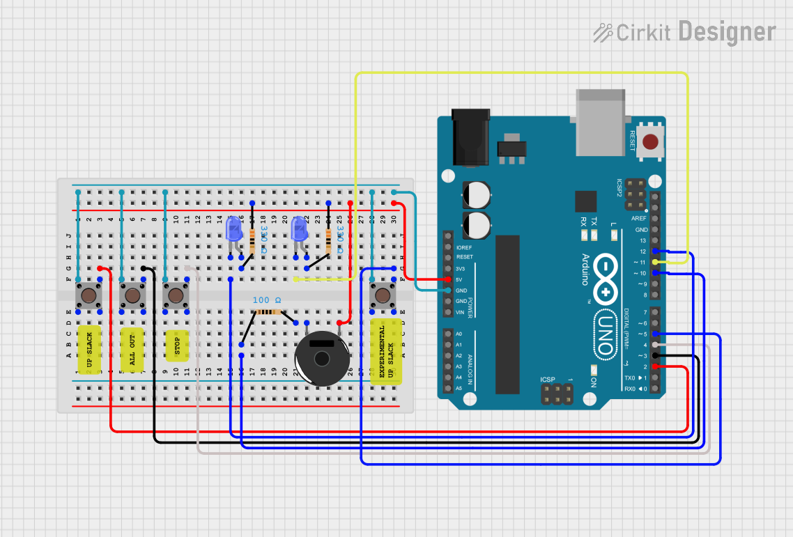
Circuit Documentation
Summary
This circuit is designed to control a winch signal lamp system using an Arduino UNO microcontroller. The system includes three control buttons (Up Slack, All Out, Stop), two blue LEDs, a piezo buzzer, and several resistors. The buttons are used to control the state of the LEDs and the buzzer, which provide visual and auditory feedback. The Arduino UNO is programmed to handle button inputs and control the outputs accordingly.
Component List
Arduino UNO
- Description: Microcontroller board based on the ATmega328P.
- Pins: UNUSED, IOREF, Reset, 3.3V, 5V, GND, Vin, A0, A1, A2, A3, A4, A5, SCL, SDA, AREF, D13, D12, D11, D10, D9, D8, D7, D6, D5, D4, D3, D2, D1, D0
Pushbutton
- Description: Simple pushbutton switch.
- Pins: Pin 3 (out), Pin 4 (out), Pin 1 (in), Pin 2 (in)
LED: Two Pin (blue)
- Description: Blue LED with two pins.
- Pins: cathode, anode
Resistor (330 Ohms)
- Description: Resistor with a resistance of 330 Ohms.
- Pins: pin1, pin2
Resistor (100 Ohms)
- Description: Resistor with a resistance of 100 Ohms.
- Pins: pin1, pin2
Piezo Buzzer
- Description: Piezoelectric buzzer.
- Pins: pin 1, pin 2
Comment
- Description: Placeholder for comments in the circuit.
- Pins: None
Wiring Details
Arduino UNO
GND is connected to:
- Pin 4 (out) of Pushbutton
- Pin 1 (in) of Pushbutton
- Pin 4 (out) of Pushbutton
- Pin 4 (out) of Pushbutton
D2 is connected to:
- Pin 2 (in) of Pushbutton
D3 is connected to:
- Pin 3 (out) of Pushbutton
D4 is connected to:
- Pin 2 (in) of Pushbutton
D5 is connected to:
- Pin 2 (in) of Pushbutton
D10 is connected to:
- pin1 of Resistor (100 Ohms)
D11 is connected to:
- cathode of LED: Two Pin (blue)
D12 is connected to:
- cathode of LED: Two Pin (blue)
5V is connected to:
- pin1 of Resistor (330 Ohms)
- pin1 of Resistor (330 Ohms)
- pin1 of Piezo Buzzer
Pushbutton
Pin 4 (out) is connected to:
- GND of Arduino UNO
- Pin 1 (in) of Pushbutton
- Pin 4 (out) of Pushbutton
- Pin 4 (out) of Pushbutton
Pin 2 (in) is connected to:
- D2 of Arduino UNO
- D4 of Arduino UNO
- D5 of Arduino UNO
Pin 3 (out) is connected to:
- D3 of Arduino UNO
LED: Two Pin (blue)
cathode is connected to:
- D12 of Arduino UNO
- D11 of Arduino UNO
anode is connected to:
- pin2 of Resistor (330 Ohms)
- pin2 of Resistor (330 Ohms)
Resistor (330 Ohms)
pin1 is connected to:
- 5V of Arduino UNO
- 5V of Arduino UNO
pin2 is connected to:
- anode of LED: Two Pin (blue)
- anode of LED: Two Pin (blue)
Resistor (100 Ohms)
- pin1 is connected to:
- D10 of Arduino UNO
Piezo Buzzer
- pin 1 is connected to:
- pin1 of Resistor (330 Ohms)
- pin1 of Resistor (330 Ohms)
- 5V of Arduino UNO
Code Documentation
/*             NVGC WINCH SIGNAL LAMP CONTROLLER MODEL
//                      v1.06   26-NOV-2024

Three control buttons -- Up Slack, All Out, Stop.
Outputs for 2 lamps & 1 buzzer.

Lamps, & buzzer connected to Vcc and activated by LOW from controller.
Buttons give LOW when pressed

*/

const int noOfButtons = 4;     //Nnumber of elements in buttonPins
const int bounceDelay = 40;    //Minimum delay before regarding a button as being pressed and debounced
const int minButtonPress = 3;  //Number of times the button has to be detected as pressed before the press is considered to be valid
const long USontime = 1000;    // Lights ON 1sec for up slack  (All time vales are in ms)
const long USofftime = 3000;   // Lights OFF 3 sec for up slack
const long AOontime = 1000;    // Lights ON 1sec for all out
const long AOofftime = 1000;   // Lights OFF 1sec for up slack
const long ALTontime = 500;    // On time for alternate flashing (Experimaental Up Slack)
const long bigDelay = 10000;    //  Big number to clear wait delay

const int buttonPins[] = {2, 3, 4, 5};      // Input pins to use, connect buttons between these pins and 0V
const int Lamp1Pin = 11;  //  I/O pins for lamps
const int Lamp2Pin = 12;
const int BuzzerPin = 10;

unsigned long previousButtonMillis[noOfButtons];       // Timers to time out bounce duration for each button
unsigned long currentLampMillis = millis();   // will store current system time in ms
unsigned long previousLampMillis = currentLampMillis;  // will store last time lamps were switched
int pressCount[noOfButtons];            // Counts the number of times the button is detected as pressed, when this count reaches minButtonPress button is regared as debounced
int buttonStates[noOfButtons];          //state of buttons, used to see value, and to see if changed
int LampsON = 1;    // Track both lamps on or off

//  Commands: 0=IDLE, 1=UP_SLACK, 2=ALL_OUT, 3=STOP,  4=Experimental Up Slack
int commandSeq = 0;   //Set initial command state to IDLE


//  ============================================================================
void setup() {
  int i;

  //setup buttonStates Array, populate with LOW
  for (i = 0; i < noOfButtons; ++i) {
    buttonStates[i] = LOW;
  }
  for (i = 0; i < noOfButtons; ++i) {
    pinMode(buttonPins[i], INPUT_PULLUP);
  }
// Set up lamp control pins and trun lamps off to start with
pinMode(Lamp1Pin, OUTPUT);
pinMode(Lamp2Pin, OUTPUT);
pinMode(BuzzerPin, OUTPUT);
digitalWrite(Lamp1Pin, HIGH);
digitalWrite(Lamp2Pin, HIGH);
digitalWrite(BuzzerPin, HIGH);

Serial.begin(9600);  //Open serial monitor for debugging
}

//  ============================================================================
void loop() {
  getButton();
  commandSeq = assignCommand();

 // Run selected lamp sequence
  switch (commandSeq) {
    case 0:     //No command -- lights OFF
    seqIDLE();
    break;
    case 1:    // Up Slack -- Short ON, long OFF
    FlashLamps(USontime,USofftime);    // then run Up Slack sequence
    break;
    case 2:    // All Out -- Short ON, Short OFF
    FlashLamps(AOontime,AOofftime);    // then run Up Slack sequence
    break;
    case 3:     // STOP  - lights ON
    seqSTOP();
    break;
    case 4:    // Alternate Up Slack -- Flash lamps alternately
    AltFlashLamps(ALTontime);    // then run Up Slack sequence
    break;
    default:     // Unrecognised command -- lights OFF
    seqIDLE();
    break;
 }
}

//  ============================================================================

void getButton() {    //Look for debounced press or release and record button no and state
  int i;
unsigned long currentMillis = millis();
  for (i = 0; i < noOfButtons; ++i) {
   int thisReading = digitalRead(buttonPins[i]);