
ESP32-S3 Battery-Powered Environmental Monitoring System with OLED Display
View and Edit Project In Cirkit Designer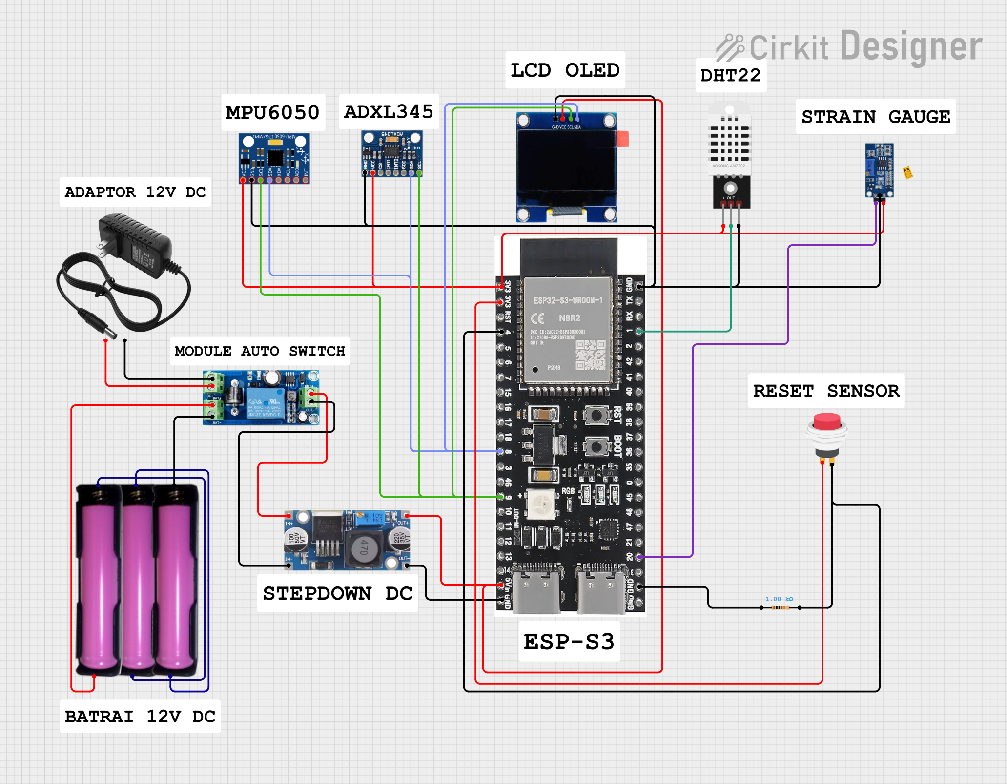
Circuit Documentation
Summary
This document provides a detailed overview of a circuit that includes various components such as an ESP32 microcontroller, sensors, a display, power supply modules, and other supporting components. The circuit is designed to interface multiple sensors and a display with the ESP32 microcontroller, powered through a UPS module and a step-down buck converter.
Component List
UPS Module
- Pins: DC-, DC+, BAT+, BAT-, OUT+, OUT-
- Description: Uninterruptible Power Supply module to ensure continuous power.
- Purpose: Provides stable power to the circuit components.
Step down Buck converter
- Pins: IN +, IN - GND, OUT +, OUT - GND
- Description: Converts higher voltage to a lower, stable voltage.
- Purpose: Supplies regulated voltage to the ESP32 and other components.
DHT22
- Pins: +, Out, -
- Description: Digital temperature and humidity sensor.
- Purpose: Measures temperature and humidity.
12v power supply
- Pins: +, -
- Description: Provides 12V DC power.
- Purpose: Powers the UPS module.
OLED 1.3"
- Pins: GND, VCC, SCL, SDA
- Description: 1.3-inch OLED display.
- Purpose: Displays information.
18650 in holder
- Pins: GND, VCC
- Description: Battery holder for 18650 cells.
- Purpose: Provides battery power.
Resistor
- Pins: pin1, pin2
- Description: 1000 Ohms resistor.
- Purpose: Used in the circuit for current limiting.
Strain Gauge Y3
- Pins: VCC, GND, OUT
- Description: Strain gauge sensor.
- Purpose: Measures strain.
ESP32-S3-DevKitC-1-N8R2
- Pins: GND, 5Vin, 14, 13, 12, 11, 10, 9, 46, 3, 8, 18, 17, 16, 15, 7, 6, 5, 4, 3v3, TX, RX, 1, 2, 42, 41, 40, 39, 38, 37, 36, 35, 0, 45, 48, 47, 21, 20, 19
- Description: ESP32 microcontroller development board.
- Purpose: Central processing unit for the circuit.
ADXL345
- Pins: GND, VCC, CS, INT1, INT2, SDO, SDA, SCL
- Description: 3-axis accelerometer.
- Purpose: Measures acceleration.
MPU-6050
- Pins: VCC, GND, SCL, SDA, XDA, XCL, AD0, INT
- Description: 6-axis motion tracking device.
- Purpose: Measures acceleration and gyroscopic data.
2Pin Push Switch
- Pins: Input +, Output +
- Description: Push button switch.
- Purpose: User input for the circuit.
Wiring Details
UPS Module
- DC-: Connected to 12v power supply (-)
- DC+: Connected to 12v power supply (+)
- BAT+: Connected to 18650 in holder (VCC)
- BAT-: Connected to 18650 in holder (GND)
- OUT+: Connected to Step down Buck converter (IN +)
- OUT-: Connected to Step down Buck converter (IN - GND)
Step down Buck converter
- IN +: Connected to UPS Module (OUT+)
- IN - GND: Connected to UPS Module (OUT-)
- OUT +: Connected to ESP32 (5Vin) and OLED 1.3" (VCC)
- OUT - GND: Connected to ESP32 (GND)
DHT22
- +: Connected to ESP32 (3v3)
- Out: Connected to ESP32 (1)
- -: Connected to ESP32 (GND)
12v power supply
- -: Connected to UPS Module (DC-)
- +: Connected to UPS Module (DC+)
OLED 1.3"
- GND: Connected to ESP32 (GND)
- VCC: Connected to Step down Buck converter (OUT +)
- SCL: Connected to ESP32 (9)
- SDA: Connected to ESP32 (8)
18650 in holder
- GND: Connected to UPS Module (BAT-)
- VCC: Connected to UPS Module (BAT+)
Resistor
- pin1: Connected to ESP32 (GND)
- pin2: Connected to ESP32 (4) and 2Pin Push Switch (Output +)
Strain Gauge Y3
- VCC: Connected to ESP32 (3v3)
- GND: Connected to ESP32 (GND)
- OUT: Connected to ESP32 (20)
ESP32-S3-DevKitC-1-N8R2
- GND: Connected to Step down Buck converter (OUT - GND), Resistor (pin1), Strain Gauge Y3 (GND), OLED 1.3" (GND), MPU-6050 (GND), DHT22 (-), ADXL345 (GND)
- 5Vin: Connected to Step down Buck converter (OUT +)
- 3v3: Connected to 2Pin Push Switch (Input +), Strain Gauge Y3 (VCC), MPU-6050 (VCC), DHT22 (+), ADXL345 (VCC)
- 9: Connected to OLED 1.3" (SCL), MPU-6050 (SCL), ADXL345 (SCL)
- 8: Connected to OLED 1.3" (SDA), MPU-6050 (SDA), ADXL345 (SDA)
- 4: Connected to Resistor (pin2) and 2Pin Push Switch (Output +)
- 1: Connected to DHT22 (Out)
- 20: Connected to Strain Gauge Y3 (OUT)
ADXL345
- GND: Connected to ESP32 (GND)
- VCC: Connected to ESP32 (3v3)
- SCL: Connected to ESP32 (9)
- SDA: Connected to ESP32 (8)
MPU-6050
- VCC: Connected to ESP32 (3v3)
- GND: Connected to ESP32 (GND)
- SCL: Connected to ESP32 (9)
- SDA: Connected to ESP32 (8)
2Pin Push Switch
- Input +: Connected to ESP32 (3v3)
- Output +: Connected to Resistor (pin2) and ESP32 (4)
Code
No code is provided for this circuit.
This document provides a comprehensive overview of the circuit, including a summary, detailed component list, wiring details, and code section. Each component is described with its purpose and connections, ensuring clarity and ease of understanding for anyone working with this circuit.