
Raspberry Pi 5 Controlled Robotic Vehicle with LIDAR and IMU
View and Edit Project In Cirkit Designer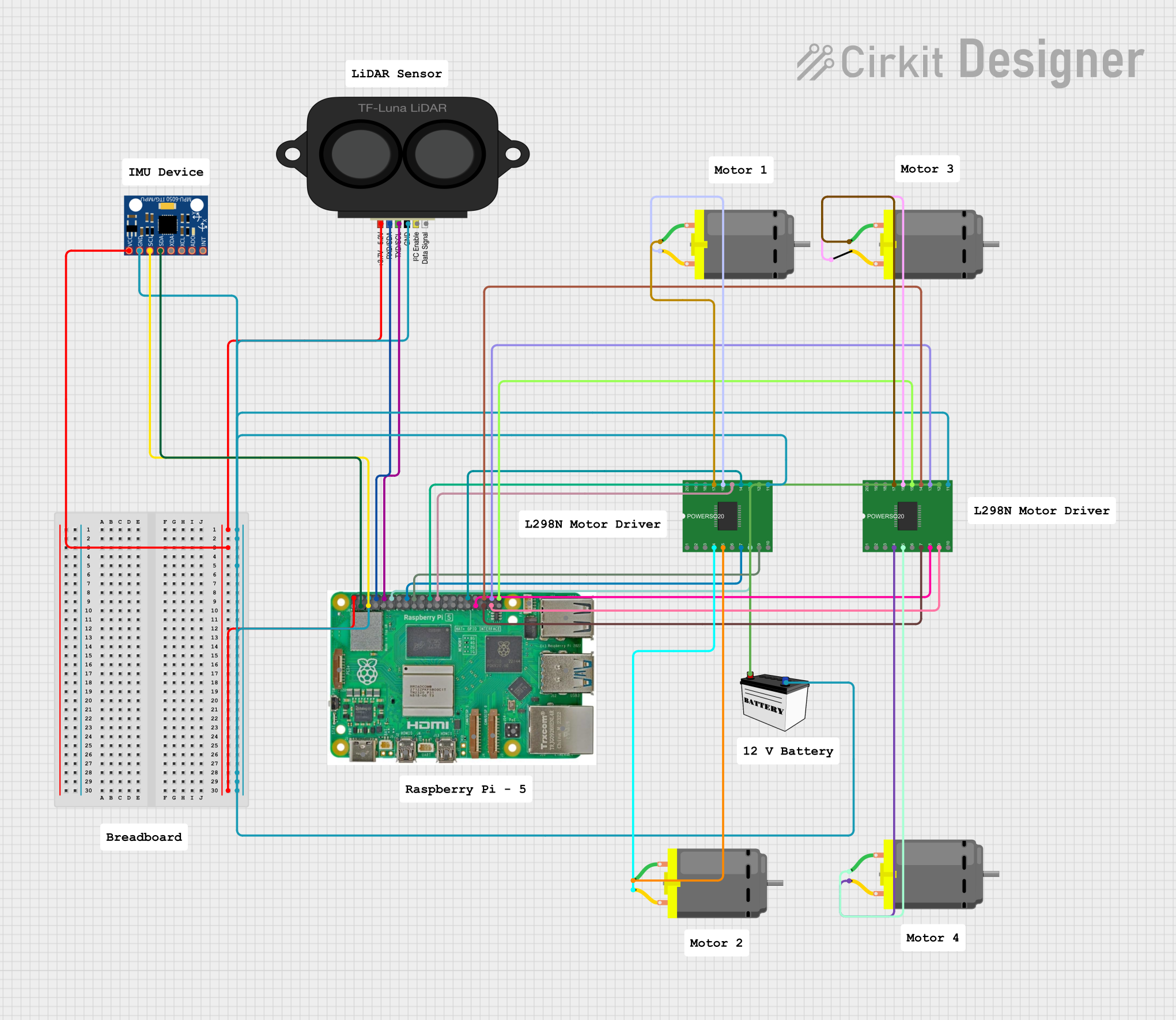
Circuit Documentation
Summary
This circuit integrates a Raspberry Pi 5 with various sensors and motor drivers to create a system capable of interfacing with LIDAR and motion sensors, as well as controlling DC motors. The Raspberry Pi 5 serves as the central processing unit, managing data from the TF LUNA LIDAR and MPU-6050 sensor, and controlling the L298 bridge drivers which in turn manage the DC motors. The circuit is powered by a 12V battery, with voltage regulation provided by the Raspberry Pi for the sensors. Ground connections are shared across all components to complete the circuit.
Component List
Raspberry Pi 5
- A microcomputer with multiple I/O pins including GPIO, USB, Ethernet, and HDMI.
- Used as the main controller for processing data and controlling other components.
TF LUNA LIDAR
- A time-of-flight (ToF) sensor module for distance measurement.
- Interfaces with the Raspberry Pi for LIDAR-based sensing applications.
MPU-6050
- A motion tracking device with a 3-axis gyroscope and a 3-axis accelerometer.
- Provides motion sensing data to the Raspberry Pi.
L298 Bridge Driver (x2)
- A motor driver module capable of driving two DC motors each.
- Used to control the speed and direction of the connected DC motors.
12V Battery (Small Size)
- Provides the power source for the motor drivers and indirectly for the entire circuit through voltage regulation by the Raspberry Pi.
DC Motor (x4)
- Converts electrical energy into mechanical motion.
- Controlled by the L298 bridge drivers for various motion applications.
Wiring Details
Raspberry Pi 5
5Vconnected to the power pins of TF LUNA LIDAR and MPU-6050 for power supply.GNDconnected to the ground pins of all components to complete the circuit.GPIO 14connected toRXD/SDAof TF LUNA LIDAR for serial data reception.GPIO 15connected toTXD/SCLof TF LUNA LIDAR for serial data transmission.GPIO 18,GPIO 23,GPIO 24,GPIO 25,GPIO 8,GPIO 12,GPIO 16,GPIO 20,GPIO 21,GPIO 13,GPIO 19,GPIO 26connected to the control pins of L298 bridge drivers for motor control.GPIO 2connected toSDAof MPU-6050 for I2C data line.GPIO 3connected toSCLof MPU-6050 for I2C clock line.
TF LUNA LIDAR
powerconnected to5Vof Raspberry Pi.GNDconnected to common ground.RXD/SDAconnected toGPIO 14of Raspberry Pi.TXD/SCLconnected toGPIO 15of Raspberry Pi.
MPU-6050
VCCconnected to5Vof Raspberry Pi.GNDconnected to common ground.SDAconnected toGPIO 2of Raspberry Pi.SCLconnected toGPIO 3of Raspberry Pi.
L298 Bridge Driver (Instance 1)
GNDconnected to common ground.ENA,IN1,IN2,IN3,IN4,ENBconnected to respective GPIO pins on Raspberry Pi for motor control.OUT1,OUT2connected to one DC Motor.OUT3,OUT4connected to another DC Motor.VSSconnected toVCCof 12V Battery for power supply.
L298 Bridge Driver (Instance 2)
GNDconnected to common ground.ENA,IN1,IN2,IN3,IN4,ENBconnected to respective GPIO pins on Raspberry Pi for motor control.OUT1,OUT2connected to one DC Motor.OUT3,OUT4connected to another DC Motor.VSSconnected toVCCof 12V Battery for power supply.
12V Battery (Small Size)
VCCconnected toVSSof both L298 bridge drivers.GNDconnected to common ground.
DC Motor (x4)
- Each motor has two pins (
pin 1andpin 2) connected to the output pins (OUT1,OUT2,OUT3,OUT4) of the L298 bridge drivers.
Documented Code
No code was provided for the microcontrollers in the circuit. The Raspberry Pi would typically be programmed using Python, C++, or another suitable language to interface with the sensors and control the motors via the GPIO pins. The code would include libraries for I2C communication, GPIO control, and potentially PWM for speed control of the motors. Since no specific code is available, this section cannot be documented further.