
Arduino Nano-Based Light Intensity Data Logger with Op-Amp Signal Conditioning
View and Edit Project In Cirkit Designer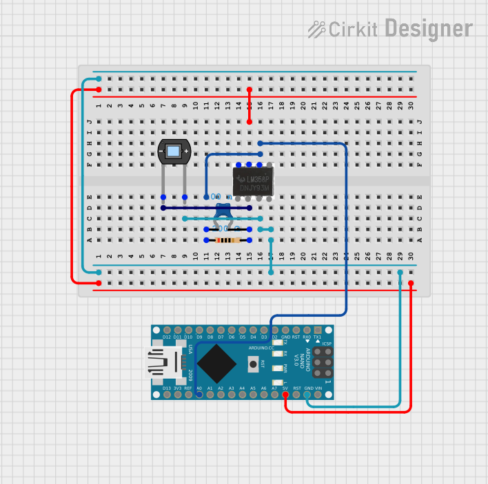
Circuit Documentation
Summary
This circuit is designed to detect light intensity using a photodiode and process the signal with an operational amplifier (op-amp) before reading the signal with an Arduino Nano microcontroller. The Arduino Nano is programmed to convert the analog signal into a digital value that represents the light intensity, which is then output as a voltage reading through serial communication.
Component List
Resistor
- Description: A resistor with a resistance value of 200 Ohms.
- Purpose: To limit current and provide biasing in the circuit.
Ceramic Capacitor
- Description: A ceramic capacitor with a capacitance value of 0.1 µF (100 nF).
- Purpose: To filter noise from the power supply or signal, and to stabilize the voltage.
Photodiode
- Description: A light-sensitive diode that generates a current proportional to light intensity.
- Purpose: To detect the intensity of light and convert it into an electrical signal.
LM358 Op-Amp
- Description: A low-power dual operational amplifier.
- Purpose: To amplify the signal from the photodiode for processing by the microcontroller.
Arduino Nano
- Description: A compact microcontroller board based on the ATmega328P.
- Purpose: To read the amplified signal from the op-amp, convert it to a digital value, and output the light intensity as a voltage reading.
Wiring Details
Resistor
- Pin 1: Connected to the output of the TIA circuit.
- Pin 2: Connected to the Ceramic Capacitor (pin 1) and the Photodiode (cathode).
Ceramic Capacitor
- Pin 0: Connected to the Resistor (pin 1), LM358 Op-Amp (pin 6), and Arduino Nano (A0).
- Pin 1: Connected to the Resistor (pin 2) and the Photodiode (cathode).
Photodiode
- Cathode: Connected to the Resistor (pin 2) and the Ceramic Capacitor (pin 1).
- Anode: Connected to the Arduino Nano (GND).
LM358 Op-Amp
- Pin 6: Connected to the Resistor (pin 1), Ceramic Capacitor (pin 0), and Arduino Nano (A0).
- Pin 7: Connected to the Arduino Nano (5V).
Arduino Nano
- A0: Connected to the Resistor (pin 1), Ceramic Capacitor (pin 0), and LM358 Op-Amp (pin 6).
- GND: Connected to the Photodiode (anode).
- 5V: Connected to the LM358 Op-Amp (pin 7).
Documented Code
// Define the analog input pin
const int sensorPin = A0;  // Connect the output of the TIA circuit to A0

// Constants
const float Vref = 5.0;        // Reference voltage of the Arduino (5V for most Arduinos)
const int ADCresolution = 1024; // 10-bit ADC resolution for Arduino Uno/Nano

void setup() {
  // Start serial communication for debugging
  Serial.begin(115200);
}

void loop() {
  // Read the analog value from the photodiode TIA output
  int sensorValue = analogRead(sensorPin);

  // Convert the ADC value to a voltage
  float voltage = (sensorValue * Vref) / ADCresolution;

  // Print the raw sensor value and the converted voltage
  Serial.print("Analog Value: ");
  Serial.print(sensorValue);
  Serial.print(" | Voltage: ");
  Serial.print(voltage, 3); // Print with 3 decimal places
  Serial.println(" V");

  // Small delay to make the output readable
  delay(1000); // Increased delay for stability
}
The code provided is for the Arduino Nano microcontroller. It initializes serial communication, reads an analog value from pin A0, converts it to a voltage, and prints the result to the serial monitor. The analog input is expected to be connected to the output of a Transimpedance Amplifier (TIA) circuit, which is not detailed in the code but is implied by the comment. The reference voltage and ADC resolution are set according to the Arduino Nano specifications.