Cirkit Designer
Your all-in-one circuit design IDE
Home /
Project Documentation
ESP32-Based Fire Alert System with LCD Display and Buzzer
Fire Alert System Circuit Documentation
Summary
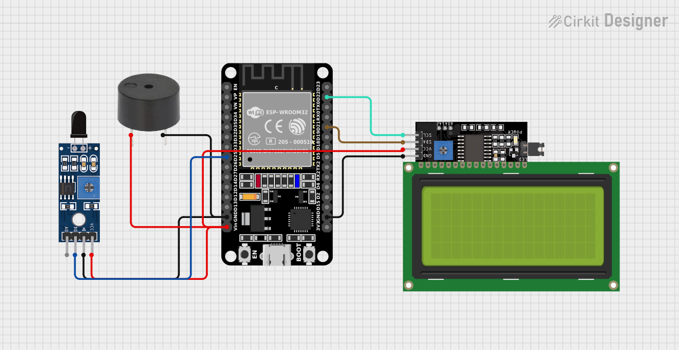
The circuit is designed to create a fire alert system using an ESP32 microcontroller, a flame sensor (Sensor SHT113 Flame), an LCD Display (20x4 I2C), and a buzzer. The ESP32 reads the flame sensor's digital output and displays the status on the LCD screen. If a flame is detected, the system activates the buzzer as an alert.
Component List
ESP32 (30 pin)
- Description: A microcontroller with WiFi and Bluetooth capabilities, featuring a wide range of GPIO pins.
- Purpose: Acts as the central processing unit of the fire alert system, reads sensor data, controls the LCD display, and drives the buzzer.
Sensor SHT113 Flame
- Description: A flame sensor capable of detecting a flame's presence and intensity.
- Purpose: Monitors for the presence of flames and provides a digital signal to the ESP32.
LCD Display 20x4 I2C
- Description: A 20x4 character LCD display with an I2C interface.
- Purpose: Displays the status of the fire alert system and messages to the user.
Buzzer
- Description: An electronic buzzer capable of emitting an audible alert.
- Purpose: Provides an audible alert when a flame is detected.
Wiring Details
ESP32 (30 pin)
- D25: Connected to the D0 pin of the Sensor SHT113 Flame (Flame sensor digital output).
- GND: Common ground shared with the Sensor SHT113 Flame, LCD Display 20x4 I2C, and buzzer.
- Vin: Connected to the VCC pins of the LCD Display 20x4 I2C, Sensor SHT113 Flame, and the PIN of the buzzer (Power supply).
- D22: Connected to the SCL pin of the LCD Display 20x4 I2C (I2C clock line).
- D21: Connected to the SDA pin of the LCD Display 20x4 I2C (I2C data line).
Sensor SHT113 Flame
- D0: Connected to the D25 pin of the ESP32 (Flame sensor digital output).
- GND: Connected to the common ground.
- VCC: Connected to the Vin pin of the ESP32 (Power supply).
LCD Display 20x4 I2C
- SCL: Connected to the D22 pin of the ESP32 (I2C clock line).
- SDA: Connected to the D21 pin of the ESP32 (I2C data line).
- VCC: Connected to the Vin pin of the ESP32 (Power supply).
- GND: Connected to the common ground.
Buzzer
- PIN: Connected to the Vin pin of the ESP32 (Power supply).
- GND: Connected to the common ground.
Documented Code
#include <LiquidCrystal_I2C.h>
#define FS 25
#define BUZ 4
LiquidCrystal_I2C lcd(0x27, 20, 4);

void setup() {
  Serial.begin(115200);
  pinMode(FS, INPUT);
  pinMode(BUZ, OUTPUT);
  lcd.init();
  lcd.backlight();
  lcd.setCursor(1, 0);    //c,r
  lcd.print("Fire Alert System");
  digitalWrite(BUZ, HIGH);
  delay(1000);
}

void loop() {
  int Flame = digitalRead(FS);
  Serial.print("Data :");
  Serial.println(Flame);
  myflame(Flame);
  mymsg(Flame);
  delay(500);
  lcd.clear();
}

void myflame(int f) {
  lcd.setCursor(1, 0);    //c,r
  lcd.print("Fire Alert System");
  lcd.setCursor(1, 2);
  lcd.print("Flame Status:");
  lcd.print(f);
  delay(500);
}

void mymsg(int f) {
  lcd.setCursor(1, 3);
  lcd.print("Message:");
  if(f == 0){
    lcd.print("Fire Alert");
    digitalWrite(BUZ, LOW);
  }
  else{
    lcd.print("Safe");
    digitalWrite(BUZ, HIGH);
  }
  delay(500);
}
Filename: sketch.ino
Description: This code initializes the ESP32 microcontroller, the LCD display, and sets up the pins for the flame sensor and buzzer. In the main loop, it reads the flame sensor's digital output and updates the LCD display with the flame status and a message. If a flame is detected, the buzzer is turned on to alert the user.