
Circuit Documentation
Summary of the Circuit
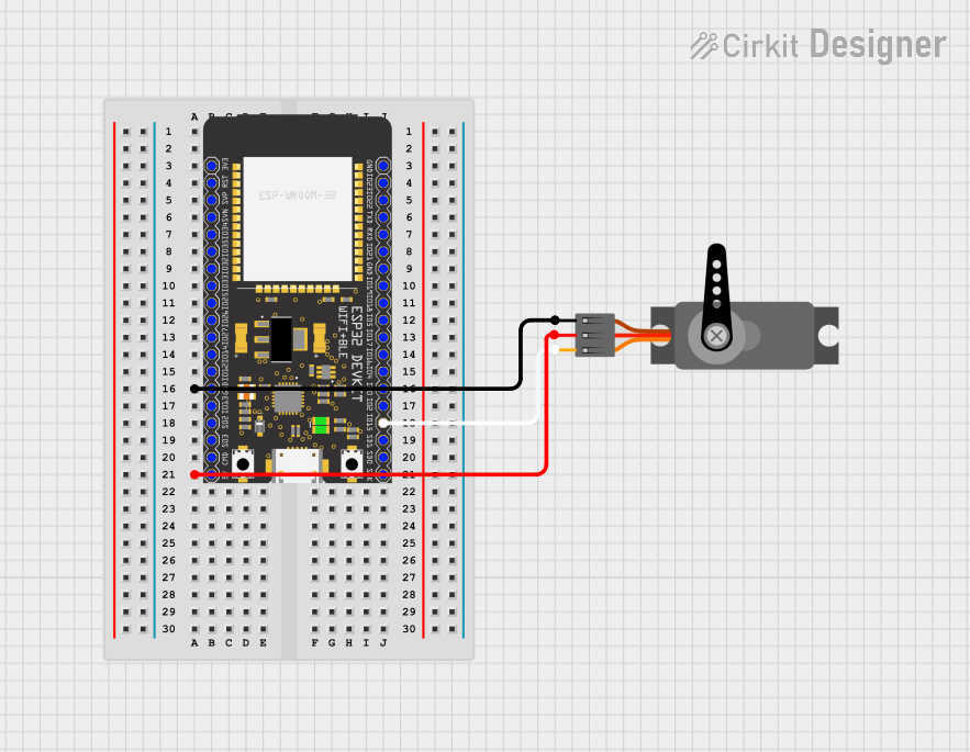
This circuit consists of an ESP32 Wroom microcontroller unit (MCU) connected to a servo motor. The ESP32 Wroom is responsible for controlling the servo motor by sending Pulse Width Modulation (PWM) signals. The servo motor is powered by a 5V supply from the ESP32 and shares a common ground with the MCU. This setup is typically used in applications where precise angular movement is required, such as in robotics or automated control systems.
Component List
ESP32 Wroom
- Description: A powerful microcontroller with Wi-Fi and Bluetooth capabilities, suitable for a wide range of applications, from low-power sensor networks to more demanding tasks such as voice encoding, music streaming, and MP3 decoding.
- Pins:
- 3V3
- Reset
- GPIO36
- GPIO39
- GPIO34
- GPIO35
- GPIO32
- GPIO33
- GPIO25
- GPIO26
- GPIO27
- GPIO14
- GPIO12
- GND
- GPIO13
- GPIO9
- GPIO10
- GPIO11
- 5V
- GPIO23
- GPIO22/SCL
- GPIO1/TXD0
- GPIO3/RXD0
- GPIO21/SDA
- GPIO19
- GPIO18
- GPIO5
- GPIO17
- GPIO16
- GPIO4
- GPIO0
- GPIO2
- GPIO15
- GPIO8
- GPIO7
- GPIO6
Servo
- Description: An actuator that can be precisely controlled for angular or linear position, velocity, and acceleration.
- Pins:
- GND
- VCC
- PWM
Wiring Details
ESP32 Wroom
- GND: Connected to the GND pin of the Servo.
- 23 (GPIO15): Connected to the PWM pin of the Servo to control it.
- 5V: Connected to the VCC pin of the Servo to power it.
Servo
- GND: Connected to the GND pin of the ESP32 Wroom.
- PWM: Connected to pin 23 (GPIO15) of the ESP32 Wroom to receive control signals.
- VCC: Connected to the 5V pin of the ESP32 Wroom for power.
Documented Code
No code has been provided for the microcontroller. Typically, the code would initialize the GPIO pin connected to the servo's PWM input and generate a PWM signal to control the servo's position. Since no code is available, it is recommended to write a program that sets up the ESP32's PWM capabilities and sends appropriate signals to the servo motor for the desired operation.