Cirkit Designer
Your all-in-one circuit design IDE
Home /
Project Documentation
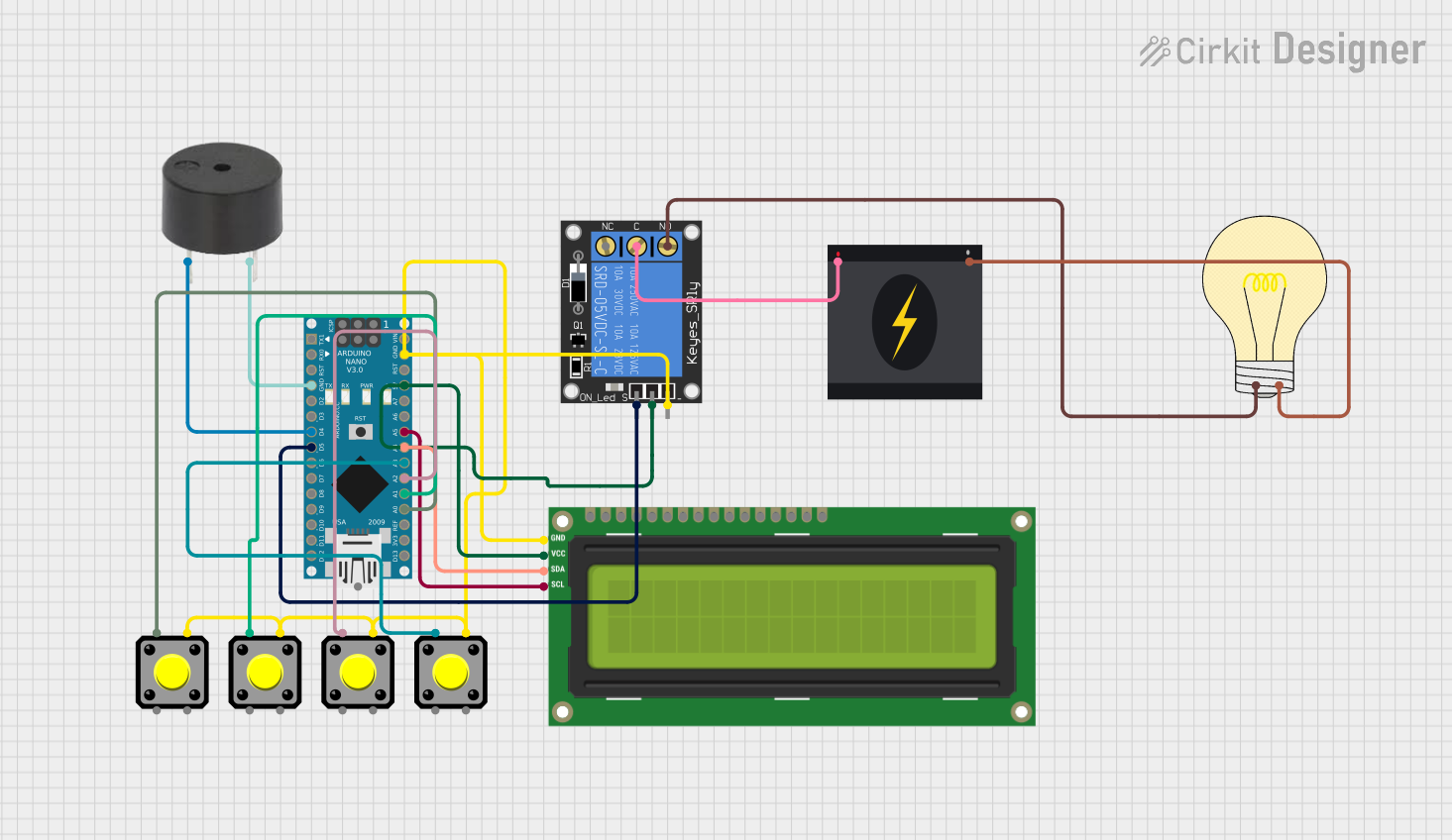
Arduino Nano Controlled Timer with Relay, Buzzer, and I2C LCD Display

Circuit Documentation
Summary
The circuit in question is designed to control a 1-Channel Relay which in turn controls a bulb, with the relay's activation being governed by an Arduino Nano microcontroller. The Arduino Nano is also interfaced with an I2C LCD 16x2 Screen for display purposes and multiple pushbuttons for user input. A buzzer is included for audible feedback. The circuit is powered by a 5V supply from the Arduino Nano, which is also connected to a 240V power source for the relay-controlled bulb.
Component List
1-Channel Relay (5V 10A)
- Description: A relay capable of switching higher power loads using a low power signal from the Arduino.
- Pins: NC (Normally Closed), signal, C (Common), power, NO (Normally Open), ground
I2C LCD 16x2 Screen
- Description: A 16x2 character LCD display that uses the I2C communication protocol for displaying information.
- Pins: SCL, SDA, VCC (5V), GND, VDD, VO, RS, RW, E, D0-D7, BLA, BLK
Pushbutton (x4)
- Description: A simple pushbutton used for user input.
- Pins: Pin 1, Pin 2, Pin 3, Pin 4
Bulb
- Description: An electrical device that emits light when a current passes through it.
- Pins: positive, negative
Buzzer
- Description: An electronic component that produces a consistent or intermittent sound when a current is applied.
- Pins: PIN, GND
Arduino Nano
- Description: A small, complete, and breadboard-friendly board based on the ATmega328 (Arduino Nano 3.x).
- Pins: D1/TX, D0/RX, RESET, GND, D2-D13, VIN, 5V, A0-A7, AREF, 3V3
240v Power Source
- Description: A power source that provides 240V AC power.
- Pins: Live, Neutral
Wiring Details
1-Channel Relay
- Signal: Connected to Arduino Nano D5
- C (Common): Connected to 240v Power Source Live
- Power: Connected to Arduino Nano 5V
- NO (Normally Open): Connected to Bulb positive
- Ground: Connected to Arduino Nano GND
I2C LCD 16x2 Screen
- SCL: Connected to Arduino Nano A5
- SDA: Connected to Arduino Nano A4
- VCC (5V): Connected to Arduino Nano 5V
- GND: Connected to Arduino Nano GND
Pushbuttons
- Pushbutton 1 Pin 1: Connected to Arduino Nano A0
- Pushbutton 2 Pin 1: Connected to Arduino Nano A1
- Pushbutton 3 Pin 1: Connected to Arduino Nano A2
- Pushbutton 4 Pin 1: Connected to Arduino Nano A3
- All Pushbutton Pin 4: Connected to Arduino Nano GND
Bulb
- Positive: Connected to 1-Channel Relay NO
- Negative: Connected to 240v Power Source Neutral
Buzzer
- PIN: Connected to Arduino Nano D4
- GND: Connected to Arduino Nano GND
Documented Code
#include <Wire.h>
#include <LiquidCrystal_I2C.h>

// Initialize LCD (16 columns, 2 rows)
LiquidCrystal_I2C lcd(0x27, 16, 2);

// Pin definitions
const int button1Pin = A0; // +10 minutes
const int button2Pin = A1; // -1 minute
const int button3Pin = A2; // +1 hour
const int button4Pin = A3; // Start/Pause/Reset

const int buzzerPin = D4;  // Buzzer
const int relayPin = D5;   // Relay module

// Timer variables
int timerDuration = 0; // in seconds
int remainingTime = 0; // in seconds
bool timerStarted = false;
bool lastButton4State = HIGH; // For detecting button press
bool buttonPressed = false;

void setup() {
  // Initialize LCD
  lcd.init();
  lcd.backlight();

  // Initialize pins
  pinMode(button1Pin, INPUT_PULLUP);
  pinMode(button2Pin, INPUT_PULLUP);
  pinMode(button3Pin, INPUT_PULLUP);
  pinMode(button4Pin, INPUT_PULLUP);
  pinMode(buzzerPin, OUTPUT);
  pinMode(relayPin, OUTPUT);
  digitalWrite(relayPin, LOW); // Ensure relay is off

  // Display initial message
  lcd.setCursor(0, 0);
  lcd.print("Timer: 00:00");
  lcd.setCursor(0, 1);
  lcd.print("Press a button");
}

void loop() {
  int button1State = digitalRead(button1Pin);
  int button2State = digitalRead(button2Pin);
  int button3State = digitalRead(button3Pin);
  int button4State = digitalRead(button4Pin);

  // Increase timer by 10 minutes
  if (button1State == LOW) {
    timerDuration += 10 * 60; // Add 10 minutes
    updateDisplay();
    delay(200); // Debounce delay
  }

  // Decrease timer by 1 minute
  if (button2State == LOW) {
    timerDuration -= 60; // Subtract 1 minute
    if (timerDuration < 0) timerDuration = 0; // Prevent negative time
    updateDisplay();
    delay(200); // Debounce delay
  }

  // Increase timer by 1 hour
  if (button3State == LOW) {
    timerDuration += 60 * 60; // Add 1 hour
    updateDisplay();
    delay(200); // Debounce delay
  }

  // Start, pause, or reset timer
  if (button4State == LOW && lastButton4State == HIGH) {
    buttonPressed = true;
    if (timerStarted) {
      timerStarted = false; // Pause timer
      digitalWrite(relayPin, LOW); // Turn off relay
      noTone(buzzerPin); // Turn off buzzer
    } else {
      if (remainingTime == 0) {
        remainingTime = timerDuration; // Reset timer if stopped
      }
      timerStarted = !timerStarted; // Toggle timer state
      digitalWrite(relayPin, timerStarted ? HIGH : LOW); // Start or stop relay
    }
    updateDisplay();
    delay(200); // Debounce delay
  }

  lastButton4State = button4State; // Update last button state

  // Timer countdown logic
  if (timerStarted) {
    if (remainingTime > 0) {
      delay(1000); // Wait for 1 second
      remainingTime--;

      int minutes = remainingTime / 60;
      int seconds = remainingTime % 60;

      lcd.setCursor(0, 0);
      lcd.print("Timer: ");
      lcd.print(minutes);
      lcd.print(":");
      if (seconds < 10) lcd.print("0");
      lcd.print(seconds);

      if (remainingTime == 0) {
        digitalWrite(relayPin, LOW); // Turn off relay
        tone(buzzerPin, 1000); // Sound buzzer
        delay(1000); // Buzzer sound duration
        noTone(buzzerPin); // Stop buzzer
        timerStarted = false; // Stop the timer
        remainingTime = 0; // Ensure time is set to 0
      }
    }
  }
}

// Update the LCD display with the current timer settings
void updateDisplay() {
  int minutes = timerDuration / 60;
  int seconds = timerDuration % 60;
  lcd.setCursor(0, 0);
  lcd.print("Timer: ");
  lcd.print(minutes);
  lcd.print(":");
  if (seconds < 10) lcd.print("0");
  lcd.print(seconds);

  if (timerStarted) {
    lcd.setCursor(0, 1);
    lcd.print("Status: Running");
  } else {
    lcd.setCursor(0, 1);
    lcd.print("Status: Paused ");
  }
}
Note: The pin definitions in the code have been updated to match the actual wiring as per the electrical net list provided. The button pins are connected to the analog inputs A0-A3, the buzzer to D4, and the relay to D5.