
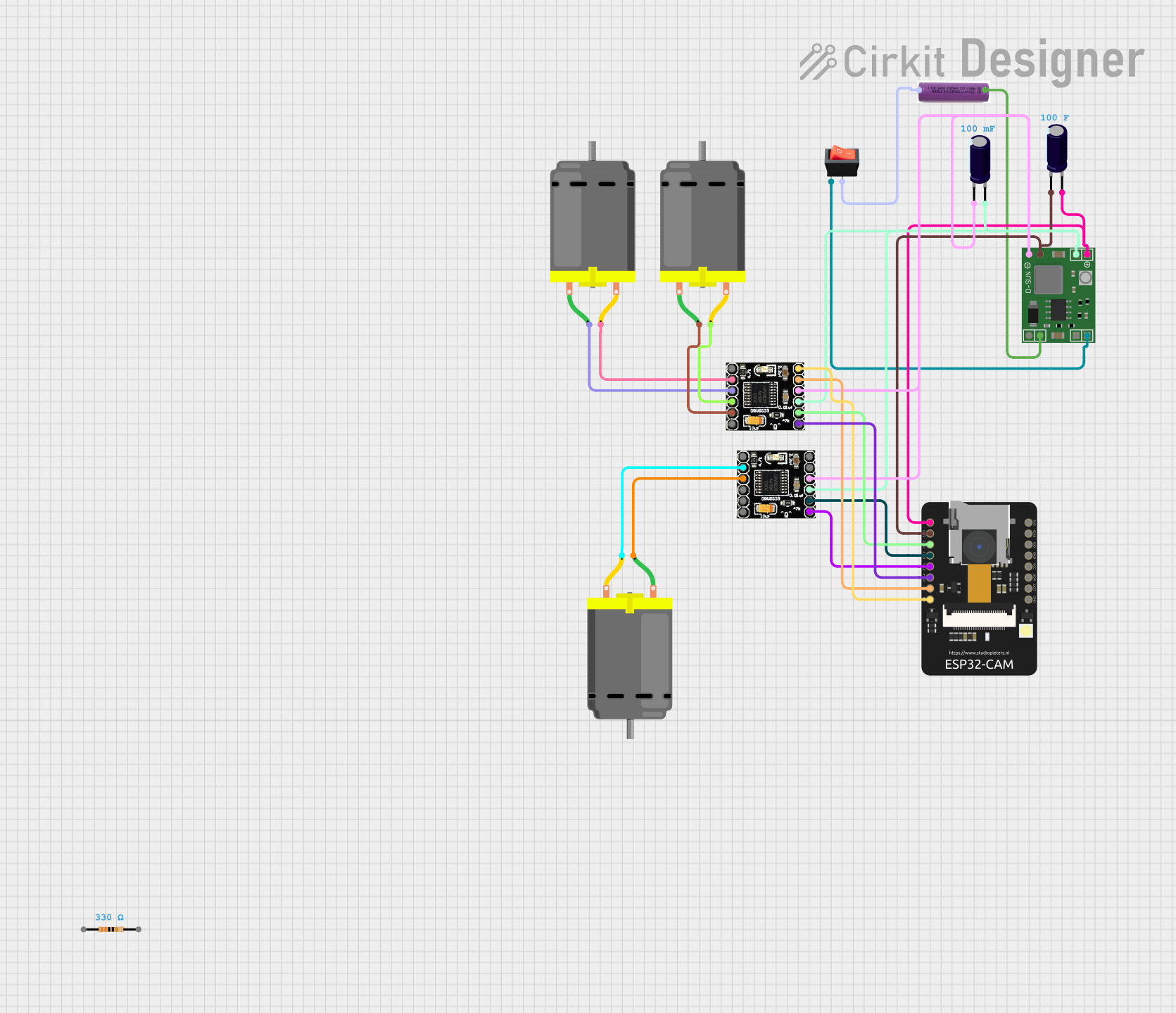
Circuit Documentation
Summary
This circuit is designed to control a vehicle with an ESP32-CAM microcontroller, which provides Wi-Fi connectivity and camera functionality. The vehicle is powered by a 3.7V battery and includes three DC motors for movement. The motors are driven by two DRV8833 motor driver ICs. A MP1584EN power regulator board steps down the voltage to power the ESP32-CAM and the motor drivers. The circuit also includes a rocker switch to control power flow and electrolytic capacitors for voltage smoothing.
Component List
ESP32-CAM
- Description: A microcontroller module with built-in Wi-Fi and camera support.
- Pins: 5V, GND, IO12, IO13, IO15, IO14, IO2, IO4, VOT, VOR, VCC, IO0, IO16, 3V3
3.7V Battery
- Description: A power source for the circuit.
- Pins: +, -
DC Motor (x3)
- Description: Motors that provide movement to the vehicle.
- Pins: pin 1, pin 2
MP1584EN Power Regulator Board
- Description: A voltage regulator that steps down the voltage for the circuit.
- Pins: IN -, IN +, OUT +, OUT -
DRV8833 Motor Driver IC (x2)
- Description: A motor driver IC that controls the speed and direction of the motors.
- Pins: EEP, OUT1, OUT2, OUT3, OUT4, ULT, IN4, IN3, GND, VCC, IN1, IN2
Rocker Switch
- Description: A switch to control the power flow in the circuit.
- Pins: output, input
Electrolytic Capacitor (x2)
- Description: Capacitors used for voltage smoothing in the circuit.
- Pins: -, +
- Properties: 100 Farads, 0.1 Farads
Resistor
- Description: A resistor to limit current or divide voltage in the circuit.
- Pins: pin1, pin2
- Properties: 330 Ohms
Wiring Details
ESP32-CAM
- 5V connected to MP1584EN Power Regulator Board (OUT +)
- GND connected to MP1584EN Power Regulator Board (OUT -)
- IO12 connected to DRV8833 (IN1)
- IO13 connected to DRV8833 (IN1)
- IO15 connected to DRV8833 (IN2)
- IO14 connected to DRV8833 (IN2)
- IO2 connected to DRV8833 (IN3)
- IO4 connected to DRV8833 (IN4)
3.7V Battery
-
- connected to Rocker Switch (output)
-
- connected to MP1584EN Power Regulator Board (IN -)
DC Motor
- pin 1 connected to DRV8833 (OUT2)
- pin 2 connected to DRV8833 (OUT1)
MP1584EN Power Regulator Board
- IN - connected to 3.7V Battery (-)
- IN + connected to Rocker Switch (input)
- OUT + connected to ESP32-CAM (5V), Electrolytic Capacitors (+), and DRV8833 (VCC)
- OUT - connected to ESP32-CAM (GND), Electrolytic Capacitors (-), and DRV8833 (GND)
DRV8833 Motor Driver IC
- VCC connected to MP1584EN Power Regulator Board (OUT +)
- GND connected to MP1584EN Power Regulator Board (OUT -)
- IN1, IN2, IN3, IN4 connected to ESP32-CAM (IO12, IO13, IO15, IO14, IO2, IO4)
- OUT1, OUT2, OUT3, OUT4 connected to DC Motors (pin 1, pin 2)
Rocker Switch
- input connected to MP1584EN Power Regulator Board (IN +)
- output connected to 3.7V Battery (+)
Electrolytic Capacitor
-
- connected to MP1584EN Power Regulator Board (OUT +)
-
- connected to MP1584EN Power Regulator Board (OUT -)
Documented Code
ESP32-CAM Code
#include "esp_camera.h"
#include <Arduino.h>
#include <WiFi.h>
#include <AsyncTCP.h>
#include <ESPAsyncWebServer.h>
#include <iostream>
#include <sstream>

// ... (Code truncated for brevity)

void setup(void)
{
  setUpPinModes();
  Serial.begin(115200);

  WiFi.softAP(ssid, password);
  IPAddress IP = WiFi.softAPIP();
  Serial.print("AP IP address: ");
  Serial.println(IP);

  server.on("/", HTTP_GET, handleRoot);
  server.onNotFound(handleNotFound);

  wsCamera.onEvent(onCameraWebSocketEvent);
  server.addHandler(&wsCamera);

  wsCarInput.onEvent(onCarInputWebSocketEvent);
  server.addHandler(&wsCarInput);

  server.begin();
  Serial.println("HTTP server started");

  setupCamera();
}

void loop()
{
  wsCamera.cleanupClients();
  wsCarInput.cleanupClients();
  sendCameraPicture();
  Serial.printf("SPIRam Total heap %d, SPIRam Free Heap %d\n", ESP.getPsramSize(), ESP.getFreePsram());
}
DRV8833 Code
void setup() {
  // put your setup code here, to run once:

}

void loop() {
  // put your main code here, to run repeatedly:

}
The ESP32-CAM code includes setup for Wi-Fi access point, web server, WebSocket for camera and car control, and motor control functions. The DRV8833 code is currently empty and would typically contain code to initialize the motor driver and control the motors based on inputs from the ESP32-CAM.