
ESP8266-Based Motion Tracking System with Wi-Fi and Relay Control
View and Edit Project In Cirkit Designer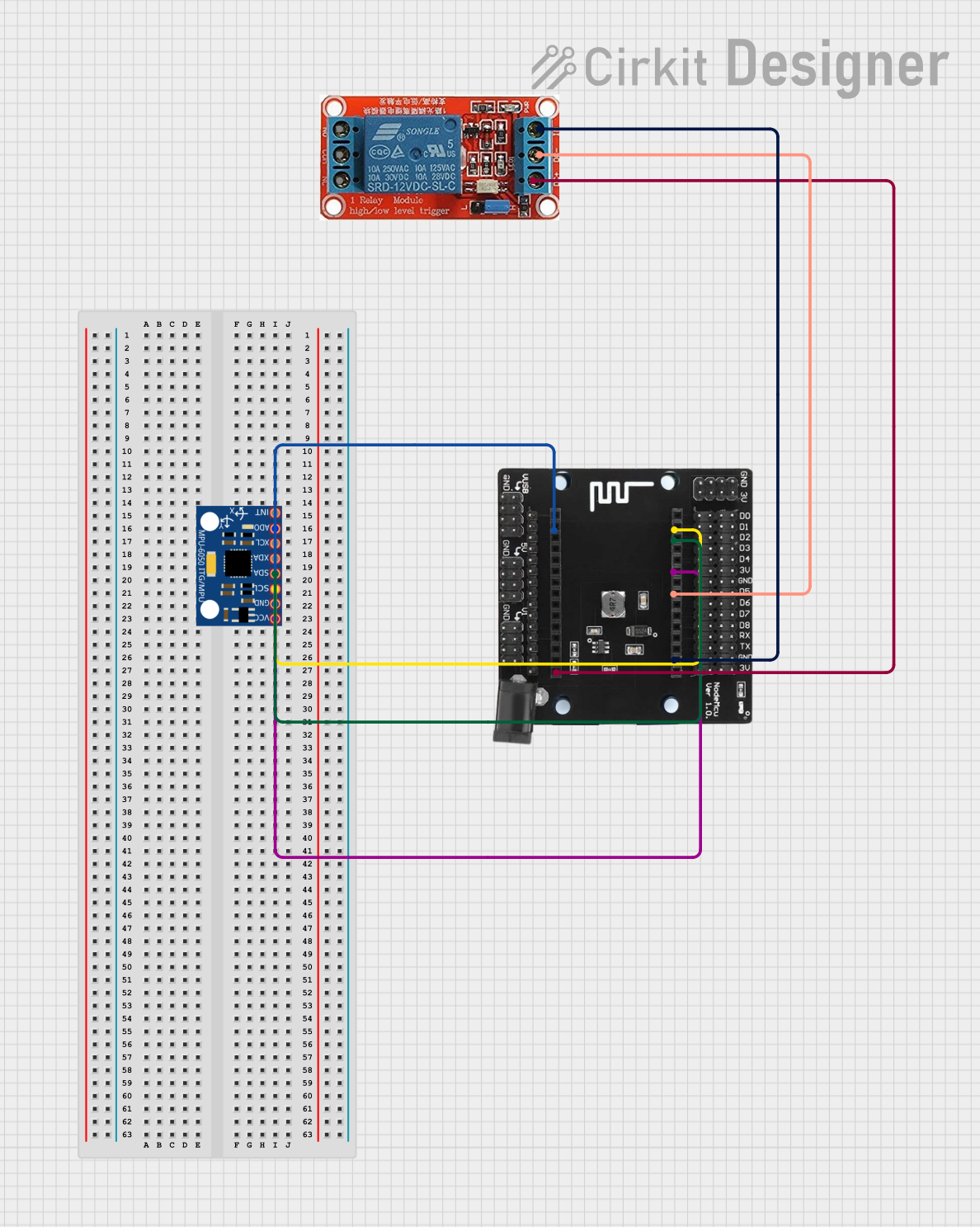
Circuit Documentation
Summary of the Circuit
This circuit integrates an ESP8266 microcontroller with an MPU-6050 accelerometer/gyroscope module and a 12V relay. The ESP8266 is responsible for processing data from the MPU-6050 and controlling the relay based on specific conditions or inputs. The MPU-6050 provides motion tracking data, while the relay enables switching of high-power devices. The ESP8266 is powered by its 3V pin, and it interfaces with the MPU-6050 via I2C communication protocol using its D1 and D2 pins as SCL and SDA lines, respectively. The relay is controlled through one of the ESP8266's GPIO pins and is powered by the VIN pin of the ESP8266.
Component List
ESP8266
- Description: A Wi-Fi capable microcontroller with multiple GPIO pins.
- Pins: 3V, G, D8, D7, D6, D5, D4, D3, D2, D1, D0, A0, S3, S2, S1, SC, S0, SK, EN, VIN, RST, VU
NodeMcu V3 Base I/O Breakout Expansion
- Description: A breakout board that provides easy access to the pins of the ESP8266.
- Pins: Not specified in the input.
MPU-6050
- Description: A motion tracking device that contains a 3-axis accelerometer and a 3-axis gyroscope.
- Pins: VCC, GND, SCL, SDA, XDA, XCL, AD0, INT
12V Relay
- Description: An electromechanical switch that allows a low-power signal to control a higher power circuit.
- Pins: NO, COM, NC, IN, DC-, DC+
Wiring Details
ESP8266
- 3V connected to MPU-6050 VCC
- G connected to MPU-6050 GND and 12V Relay IN
- D1 (SCL) connected to MPU-6050 SCL
- D2 (SDA) connected to MPU-6050 SDA
- D5 connected to 12V Relay DC-
- VIN connected to 12V Relay DC+
MPU-6050
- VCC connected to ESP8266 3V
- GND connected to ESP8266 G
- SCL connected to ESP8266 D1
- SDA connected to ESP8266 D2
12V Relay
- IN connected to ESP8266 G
- DC- connected to ESP8266 D5
- DC+ connected to ESP8266 VIN
Documented Code
No code was provided in the input. Therefore, there is no code documentation available for this circuit. If code becomes available, it should be documented here with explanations of how the microcontroller interfaces with the MPU-6050 and the relay, including any initialization, data processing, and control logic.