
Circuit Documentation
Summary
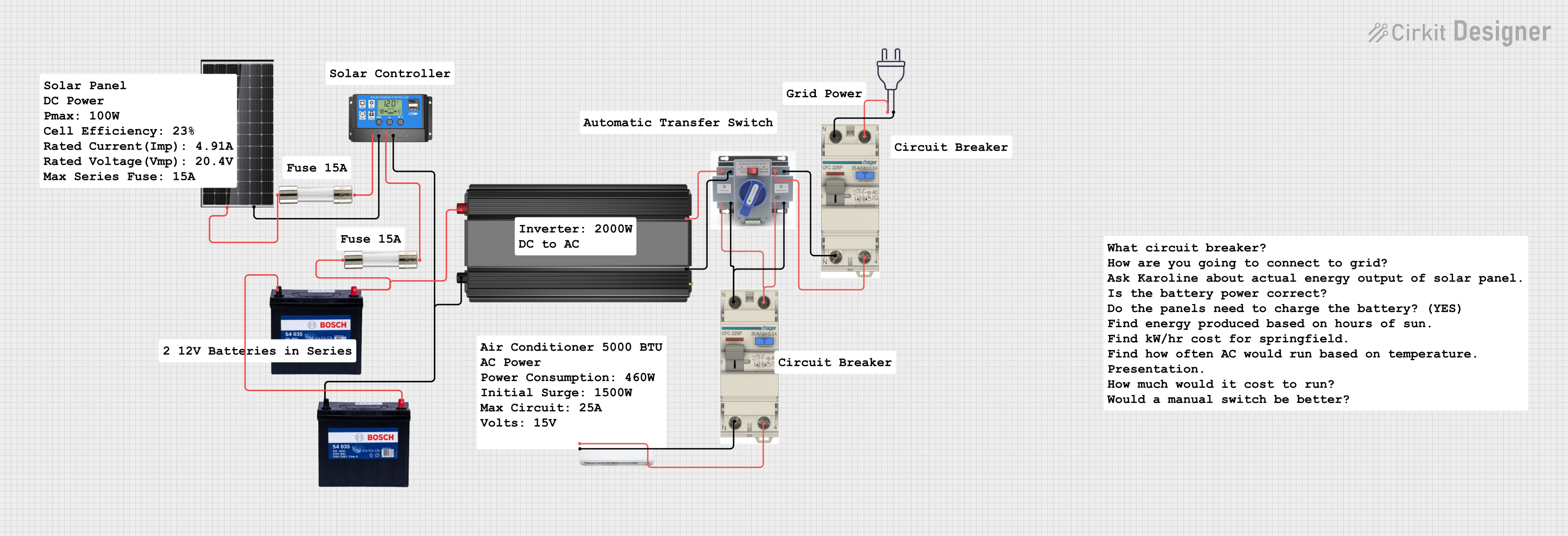
This document provides a detailed overview of a solar power system circuit. The circuit includes a solar panel, a battery, a solar charge controller, a power inverter, fuses, an automatic transfer switch (ATS), an AC circuit breaker, and an air conditioner. The system is designed to harness solar energy, store it in a battery, and convert it to AC power for use with household appliances.
Component List
Solar Panel 380W
- Pins: -, +
- Description: Converts sunlight into electrical energy.
12V 200Ah Battery
- Pins: GND, 12V
- Description: Stores electrical energy for later use.
Solar Charge Controller
- Pins: Solar Cell +, Solar Cell -, Battery +, Battery -, Load +, Load -
- Description: Manages the power going into and coming out of the battery to prevent overcharging and over-discharging.
Power Inverter
- Pins: -, +
- Description: Converts DC power from the battery to AC power for household appliances.
Fuse
- Pins: Terminal 1, Terminal 2
- Description: Protects the circuit by breaking the connection if the current exceeds a certain threshold.
Power 220V
- Pins: hot wire, neutral wire
- Description: Provides AC power from the grid.
ATS (Automatic Transfer Switch)
- Pins: +, -
- Description: Automatically switches between power sources.
AC Circuit Breaker
- Pins: GND, VOUT, VIN
- Description: Protects the AC circuit by breaking the connection if the current exceeds a certain threshold.
Air Conditioner
- Pins: +, -
- Description: Consumes AC power to provide cooling.
Wiring Details
Solar Panel 380W
- Pin + is connected to Terminal 1 of a Fuse.
- Pin - is connected to Solar Cell - of the Solar Charge Controller.
12V 200Ah Battery
- Pin GND is connected to GND of another 12V 200Ah Battery.
- Pin 12V is connected to Terminal 1 of a Fuse and + of the Power Inverter.
- Pin GND is also connected to Battery - of the Solar Charge Controller and - of the Power Inverter.
Solar Charge Controller
- Pin Solar Cell + is connected to Terminal 2 of a Fuse.
- Pin Solar Cell - is connected to - of the Solar Panel 380W.
- Pin Battery + is connected to Terminal 2 of another Fuse.
- Pin Battery - is connected to GND of the 12V 200Ah Battery.
- Pin Load + and Load - are not connected in this circuit.
Power Inverter
- Pin + is connected to Terminal 1 of a Fuse and + of the ATS.
- Pin - is connected to Battery - of the Solar Charge Controller and - of the ATS.
Fuse
- Terminal 1 of the first Fuse is connected to + of the Solar Panel 380W.
- Terminal 2 of the first Fuse is connected to Solar Cell + of the Solar Charge Controller.
- Terminal 1 of the second Fuse is connected to 12V of the 12V 200Ah Battery.
- Terminal 2 of the second Fuse is connected to Battery + of the Solar Charge Controller.
Power 220V
- Pin hot wire is connected to VIN of the AC Circuit Breaker.
- Pin neutral wire is connected to GND of the AC Circuit Breaker.
ATS (Automatic Transfer Switch)
- Pin + is connected to + of the Power Inverter and VIN of the AC Circuit Breaker.
- Pin - is connected to - of the Power Inverter and GND of the AC Circuit Breaker.
AC Circuit Breaker
- Pin GND is connected to neutral wire of the Power 220V and - of the ATS.
- Pin VIN is connected to hot wire of the Power 220V and + of the ATS.
- Pin VOUT is connected to + of the ATS and + of the Air Conditioner.
Air Conditioner
- Pin + is connected to VOUT of the AC Circuit Breaker.
- Pin - is connected to GND of the AC Circuit Breaker.
Code
There is no embedded code provided for this circuit.
This document provides a comprehensive overview of the solar power system circuit, including a summary, component list, wiring details, and code documentation.