
Arduino UNO Controlled Security System with IR Sensors and LCD Display
View and Edit Project In Cirkit Designer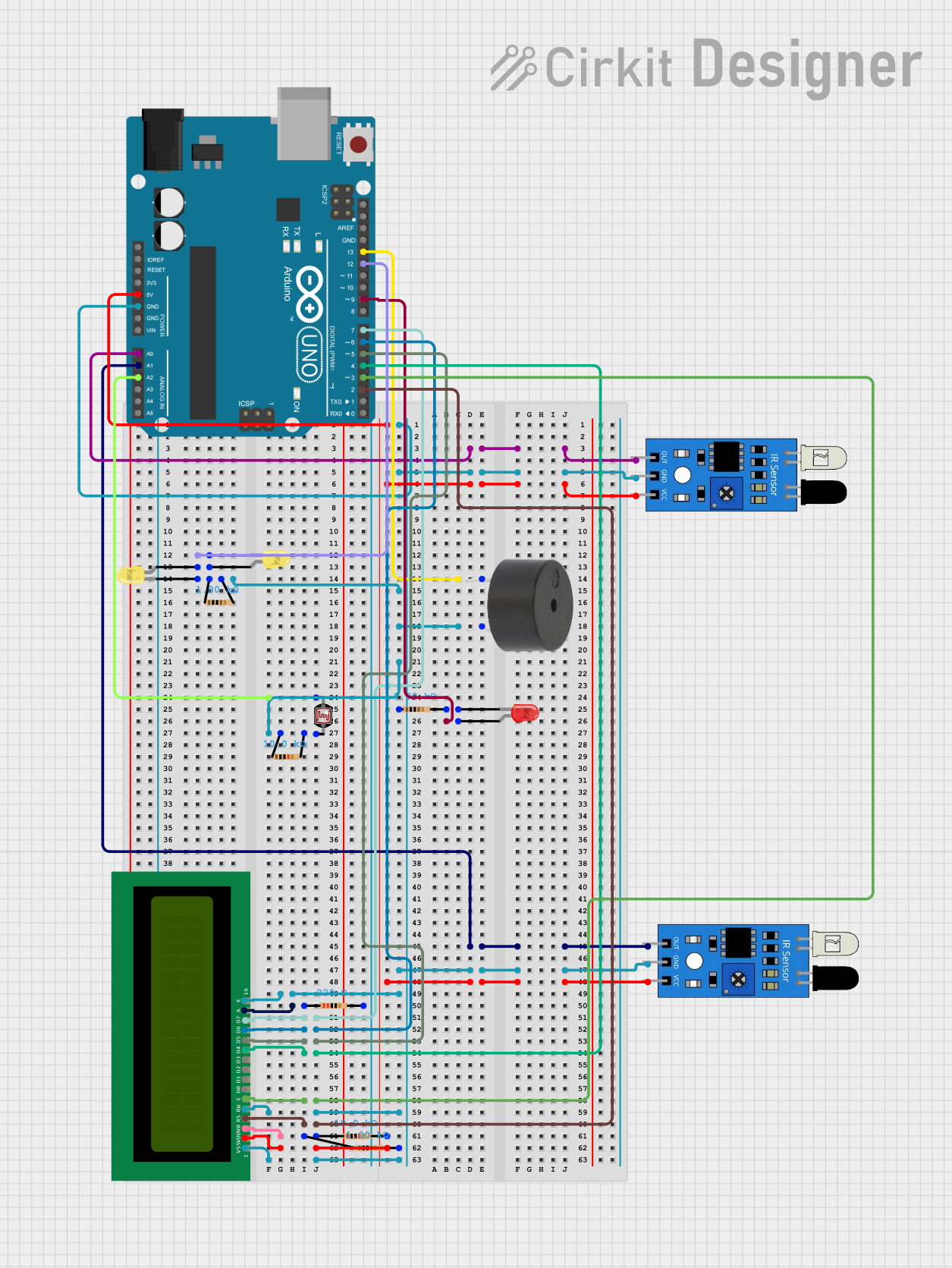
Circuit Documentation
Summary
The circuit in question is designed to interface an Arduino UNO with a variety of components including a 16x2 LCD, two IR sensors, a buzzer, multiple LEDs (red and yellow), several resistors, and a photocell (LDR). The Arduino UNO serves as the central microcontroller, managing inputs from the IR sensors and the photocell, and controlling outputs to the LCD, buzzer, and LEDs. The circuit appears to be set up for some form of sensor-based input with visual and auditory output.
Component List
16X2 LCD
- Description: A liquid crystal display capable of showing 16 characters per 2 lines.
- Pins: VSS, VDD, V0, RS, RW, E, D0-D7, A, K.
Arduino UNO
- Description: A microcontroller board based on the ATmega328P.
- Pins: IOREF, Reset, 3.3V, 5V, GND, Vin, A0-A5, SCL, SDA, AREF, D0-D13.
IR Sensor
- Description: An infrared sensor for detecting proximity or measuring intensity of IR light.
- Pins: out, gnd, vcc.
Buzzer
- Description: An electromechanical component that produces sound.
- Pins: PIN, GND.
LED: Two Pin (Red)
- Description: A red light-emitting diode.
- Pins: cathode, anode.
LED: Two Pin (Yellow)
- Description: A yellow light-emitting diode.
- Pins: cathode, anode.
Resistor
- Description: A passive two-terminal electrical component that implements electrical resistance.
- Values: 220 Ohms, 1000 Ohms, 10000 Ohms.
Photocell (LDR)
- Description: A light-dependent resistor whose resistance decreases with increasing incident light intensity.
- Pins: pin 0, pin 1.
Wiring Details
16X2 LCD
- VSS, RW, K connected to GND.
- VDD connected to 5V.
- V0 connected to the middle of a voltage divider formed by two 1000 Ohm resistors.
- RS connected to D2.
- E connected to D3.
- D4 to D7 connected to D4 to D7 on the Arduino UNO respectively.
- A connected to a 220 Ohm resistor.
Arduino UNO
- A0 connected to IR sensor out.
- A1 connected to another IR sensor out.
- A2 connected to Photocell pin 0.
- D2 to D7 connected to corresponding LCD pins.
- D9 connected to the anode of a red LED through a 1000 Ohm resistor.
- D12 connected to the anode of a yellow LED.
- D13 connected to the buzzer PIN.
- GND connected to various components' ground pins.
- 5V connected to various components' VCC pins.
IR Sensor
- Out connected to A0 or A1 on the Arduino UNO.
- Gnd connected to GND.
- Vcc connected to 5V.
Buzzer
- PIN connected to D13 on the Arduino UNO.
- GND connected to GND.
LED: Two Pin (Red)
- Anode connected to D9 on the Arduino UNO through a 1000 Ohm resistor.
- Cathode connected to GND.
LED: Two Pin (Yellow)
- Anode of one LED connected to D12 on the Arduino UNO.
- Anode of the other LED connected to the anode of the first yellow LED.
- Cathode connected to GND.
Resistor
- Various resistors used for pull-ups, pull-downs, current limiting, and voltage dividing.
Photocell (LDR)
- Pin 0 connected to A2 on the Arduino UNO.
- Pin 1 connected to GND through a 10000 Ohm resistor.
Documented Code
void setup() {
  // put your setup code here, to run once:

}

void loop() {
  // put your main code here, to run repeatedly:

}
Note: The provided code is a template and does not contain any functional code specific to the circuit. The user is expected to fill in the setup and loop functions with code to initialize the components and define the circuit's behavior.