
Arduino-Based Medication Reminder with Hall Sensor and Wi-Fi Connectivity
View and Edit Project In Cirkit Designer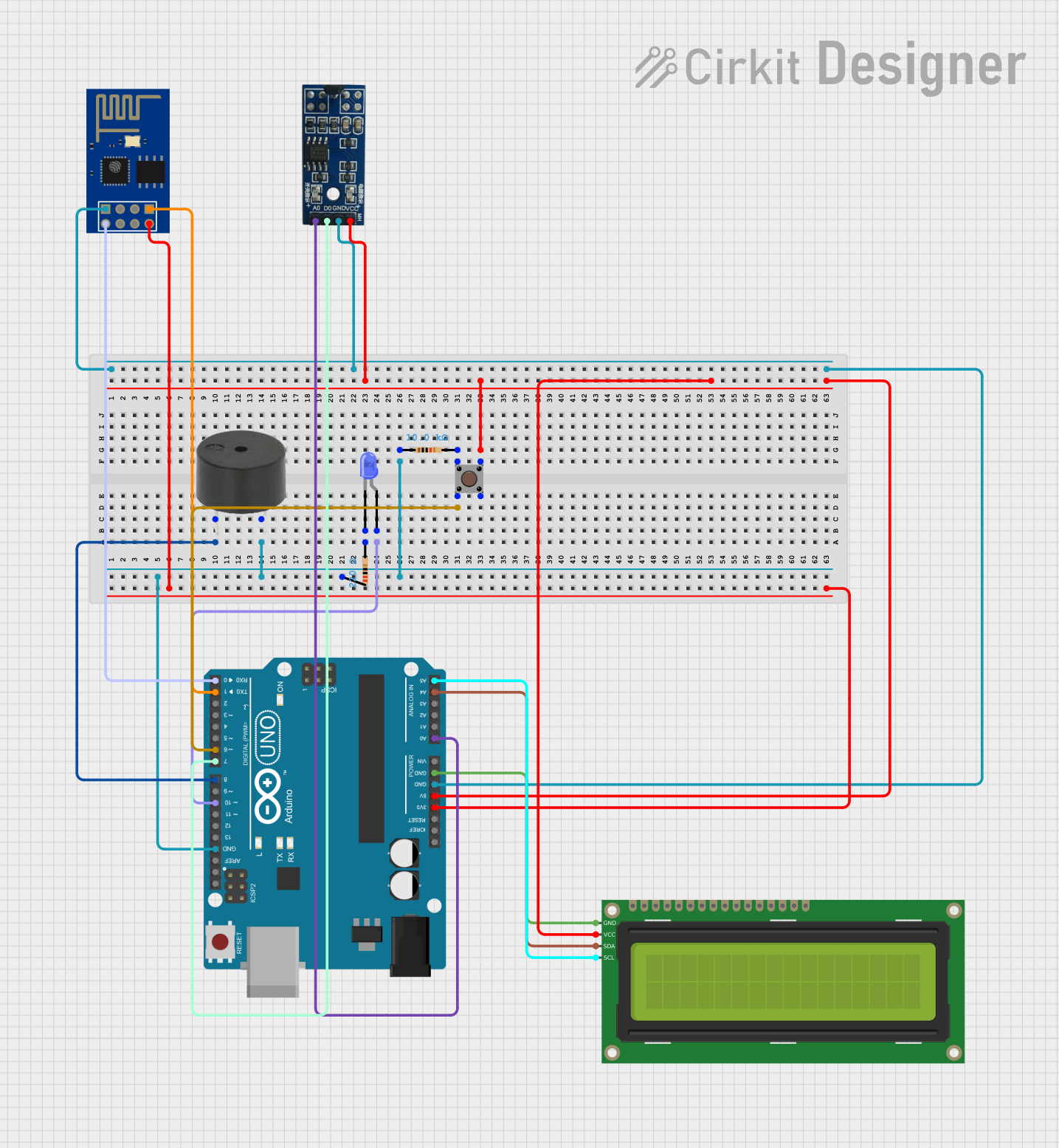
Circuit Documentation
Summary
This circuit is designed to function as a reminder system for taking Antiretroviral (ARV) medication. It utilizes an Arduino UNO microcontroller to control various components including a buzzer, an LED, a pushbutton, a Hall sensor, an I2C LCD display, and an ESP8266 WiFi module. The system detects the presence of a magnetic field using the Hall sensor and provides visual and auditory reminders through the LED and buzzer. The pushbutton is used to reset the reminder interval.
Component List
Arduino UNO
- Description: Microcontroller board based on the ATmega328P.
- Pins: UNUSED, IOREF, Reset, 3.3V, 5V, GND, Vin, A0, A1, A2, A3, A4, A5, SCL, SDA, AREF, D13, D12, D11, D10, D9, D8, D7, D6, D5, D4, D3, D2, D1, D0
Buzzer
- Description: A simple piezoelectric buzzer.
- Pins: PIN, GND
16x2 I2C LCD
- Description: A 16x2 character LCD display with I2C interface.
- Pins: GND, VCC, SDA, SCL
LED: Two Pin (blue)
- Description: A blue LED with two pins.
- Pins: cathode, anode
Resistor (220 Ohms)
- Description: A resistor with a resistance of 220 Ohms.
- Pins: pin1, pin2
Resistor (10k Ohms)
- Description: A resistor with a resistance of 10k Ohms.
- Pins: pin1, pin2
ESP8266 ESP-01 WiFi Module
- Description: A WiFi module based on the ESP8266 chip.
- Pins: TXD, CH_PD, RST, VCC, GND, GPIO_2, GPIO_0, RXD
Pushbutton
- Description: A simple pushbutton switch.
- Pins: Pin 3 (out), Pin 4 (out), Pin 1 (in), Pin 2 (in)
Hall sensor (magnetic)
- Description: A sensor that detects magnetic fields.
- Pins: VCC (5V), GND, D0 (Digital), A0 (Analog)
Wiring Details
Arduino UNO
- D8: Connected to PIN of the Buzzer
- GND: Connected to GND of the Buzzer, pin1 of the 220 Ohm Resistor, pin1 of the 10k Ohm Resistor, GND of the ESP8266, GND of the Hall sensor, and GND of the LCD
- D10: Connected to anode of the LED
- D6: Connected to Pin 2 (in) of the Pushbutton
- 5V: Connected to VCC of the Hall sensor, VCC of the LCD, and Pin 3 (out) of the Pushbutton
- 3.3V: Connected to VCC of the ESP8266
- A0: Connected to A0 (Analog) of the Hall sensor
- A4: Connected to SDA of the LCD
- A5: Connected to SCL of the LCD
- D7: Connected to D0 (Digital) of the Hall sensor
- D1: Connected to RXD of the ESP8266
- D0: Connected to TXD of the ESP8266
Buzzer
- PIN: Connected to D8 of the Arduino UNO
- GND: Connected to GND of the Arduino UNO and pin1 of the 220 Ohm Resistor
16x2 I2C LCD
- GND: Connected to GND of the Arduino UNO
- VCC: Connected to 5V of the Arduino UNO
- SDA: Connected to A4 of the Arduino UNO
- SCL: Connected to A5 of the Arduino UNO
LED: Two Pin (blue)
- anode: Connected to D10 of the Arduino UNO
- cathode: Connected to pin2 of the 220 Ohm Resistor
Resistor (220 Ohms)
- pin1: Connected to GND of the Arduino UNO and GND of the Buzzer
- pin2: Connected to cathode of the LED
Resistor (10k Ohms)
- pin1: Connected to GND of the Arduino UNO
- pin2: Connected to Pin 1 (in) of the Pushbutton
ESP8266 ESP-01 WiFi Module
- GND: Connected to GND of the Arduino UNO
- VCC: Connected to 3.3V of the Arduino UNO
- RXD: Connected to D1 of the Arduino UNO
- TXD: Connected to D0 of the Arduino UNO
Pushbutton
- Pin 2 (in): Connected to D6 of the Arduino UNO
- Pin 3 (out): Connected to VCC of the Hall sensor, VCC of the LCD, and 5V of the Arduino UNO
- Pin 1 (in): Connected to pin2 of the 10k Ohm Resistor
Hall sensor (magnetic)
- VCC (5V): Connected to 5V of the Arduino UNO and Pin 3 (out) of the Pushbutton
- GND: Connected to GND of the Arduino UNO
- D0 (Digital): Connected to D7 of the Arduino UNO
- A0 (Analog): Connected to A0 of the Arduino UNO
Code Documentation
#include <Wire.h>
#include <LiquidCrystal_I2C.h>

LiquidCrystal_I2C lcd(0x27, 16, 2); // Adresse I2C pour le LCD

const int hallDO = 7;
const int hallA0 = A0;
const int buzzerPin = 8;
const int buttonPin = 6;
const int ledPin = 10;

unsigned long lastInteraction = 0;
const unsigned long reminderInterval = 24 * 60 * 60 * 1000; // Avec une ntervalle de rappel de 24h

void setup() {

  lcd.init();
  lcd.backlight();
  lcd.print("ARV Reminder");
  delay(2000);
  lcd.clear();

  pinMode(hallDO, INPUT);
  pinMode(buzzerPin, OUTPUT);
  pinMode(buttonPin, INPUT_PULLUP);
  pinMode(ledPin, OUTPUT);

  // Message de démarrage
  lcd.setCursor(0, 0);
  lcd.print("System Ready");
  delay(2000);
  lcd.clear();
}

void loop() {

  int hallDigitalState = digitalRead(hallDO);
  int hallAnalogValue = analogRead(hallA0);
  int buttonState = digitalRead(buttonPin);

  if (buttonState == LOW) {
    lastInteraction = millis();
    lcd.setCursor(0, 0);
    lcd.print("Bouton presse! ");
    delay(500);

  // Détection d'un aimant (couvercle fermé)
  if (hallDigitalState == LOW) {
    lastInteraction = millis();
    lcd.setCursor(0, 0);
    lcd.print("Dose prise     ");
    noTone(buzzerPin);
    digitalWrite(ledPin, LOW);
  }
  // Si aucun aimant n'est détecté pendant longtemps (couvercle ouvert)
  else if (millis() - lastInteraction > reminderInterval) {
    lcd.setCursor(0, 0);
    lcd.print("Prendre ARV    ");
    tone(buzzerPin, 1000);
    digitalWrite(ledPin, HIGH);
  }
  else {
    lcd.setCursor(0, 0);
    lcd.print("En attente...  ");
    noTone(buzzerPin);
    digitalWrite(ledPin, LOW);
  }

  // Afficher la valeur analogique sur le LCD
  lcd.setCursor(0, 1);
  lcd.print("Magnet: ");
  lcd.print(hallAnalogValue);

  delay(1000);
}
This code initializes the LCD, sets up the pins, and continuously checks the state of the Hall sensor and the pushbutton. It provides visual feedback on the LCD and auditory feedback through the buzzer based on the state of the Hall sensor and the elapsed time since the last interaction.