
STM32F103C8T6 and ESP8266-Based Real-Time Crop Health Monitoring System with Wi-Fi Connectivity
View and Edit Project In Cirkit Designer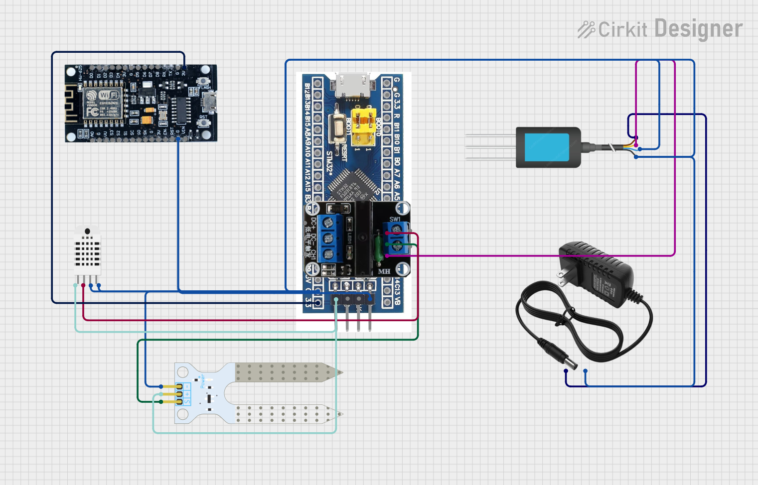
Real-Time Crop Health Monitoring System
Summary
This circuit is designed for real-time monitoring of crop health using various sensors. The system reads data from an NPK Soil Sensor, a Soil Moisture Sensor, and a Humidity and Temperature Sensor. The data is processed by an STM32F103C8T6 microcontroller and transmitted wirelessly via an ESP8266 module. The system is powered by a 12V power supply and includes a Solid State Relay for controlling external devices.
Component List
STM32F103C8T6
- Description: Microcontroller used for processing sensor data.
- Pins: GND, 3.3V, reset, B11, B10, B1, B0, A7, A6, A5, A4, A3, A2, A1, A0, C15, C14, C13, VBT, 3.3, 5V, B12, B13, b14, B15, A8, A9, A10, A11, A12, A15, B3, B4, B5, B6, B7, B8, B9, SWIO, SWCLK
Solid State Relay 1x
- Description: Relay used for controlling external devices.
- Pins: CH1, DC-, DC+
ESP8266
- Description: WiFi module used for wireless data transmission.
- Pins: 3V, G, D8, D7, D6, D5, D4, D3, D2, D1, D0, A0, S3, S2, S1, SC, S0, SK, EN, VIN, RST, VU
Humidity and Temperature Sensor (RHT03)
- Description: Sensor used for measuring humidity and temperature.
- Pins: Vcc, Data-signal, GND 1, GND 2
Soil Moisture Sensor
- Description: Sensor used for measuring soil moisture levels.
- Pins: VCC, GND, SIG
NPK Soil Sensor
- Description: Sensor used for measuring soil nutrient levels (NPK).
- Pins: 12V DC, A, B, GND
12V Power Supply
- Description: Power supply for the circuit.
- Pins: +, -
Wiring Details
STM32F103C8T6
- A2: Connected to Data-signal of Humidity and Temperature Sensor (RHT03)
- A1: Connected to SIG of Soil Moisture Sensor
- A0: Connected to A of NPK Soil Sensor
- 3.3: Connected to 3V of ESP8266
- GND: Connected to GND of Humidity and Temperature Sensor (RHT03), Soil Moisture Sensor, ESP8266, NPK Soil Sensor, and 12V Power Supply
- 3.3V: Connected to Vcc of Humidity and Temperature Sensor (RHT03) and VCC of Soil Moisture Sensor
Solid State Relay 1x
- CH1: Not connected in this circuit
- DC-: Not connected in this circuit
- DC+: Not connected in this circuit
ESP8266
- 3V: Connected to 3.3 of STM32F103C8T6
- G: Connected to GND of STM32F103C8T6
Humidity and Temperature Sensor (RHT03)
- Vcc: Connected to 3.3V of STM32F103C8T6
- Data-signal: Connected to A2 of STM32F103C8T6
- GND 1: Connected to GND of STM32F103C8T6
- GND 2: Connected to GND of STM32F103C8T6
Soil Moisture Sensor
- VCC: Connected to 3.3V of STM32F103C8T6
- GND: Connected to GND of STM32F103C8T6
- SIG: Connected to A1 of STM32F103C8T6
NPK Soil Sensor
- 12V DC: Connected to + of 12V Power Supply
- A: Connected to A0 of STM32F103C8T6
- B: Connected to GND of STM32F103C8T6
- GND: Connected to GND of STM32F103C8T6
12V Power Supply
- +: Connected to 12V DC of NPK Soil Sensor
- -: Connected to GND of STM32F103C8T6
Code Documentation
/*
 * Real-Time Crop Health Monitoring System
 * This Arduino sketch reads data from various sensors (NPK Soil Sensor, Soil Moisture Sensor,
 * and Humidity and Temperature Sensor) connected to an STM32F103C8T6 microcontroller.
 * The data is then sent to an ESP8266 module for wireless transmission to a dashboard or
 * mobile app interface for farmers to view real-time crop health updates.
 * Objectives:
 * - Optimize memory usage for storing sensor data in RAM and ROM
 * - Implement an energy-efficient system to maximize battery life
 */

#include <Wire.h>
#include <ESP8266WiFi.h>
#include <LowPower.h>

// Pin definitions
#define NPK_SOIL_SENSOR_PIN A0
#define SOIL_MOISTURE_SENSOR_PIN A1
#define HUMIDITY_TEMP_SENSOR_PIN A2

// WiFi credentials
const char* ssid = "your_SSID";
const char* password = "your_PASSWORD";

void setup() {
  // Initialize serial communication
  Serial.begin(9600);
  // Initialize sensor pins
  pinMode(NPK_SOIL_SENSOR_PIN, INPUT);
  pinMode(SOIL_MOISTURE_SENSOR_PIN, INPUT);
  pinMode(HUMIDITY_TEMP_SENSOR_PIN, INPUT);
  // Connect to WiFi
  WiFi.begin(ssid, password);
  while (WiFi.status() != WL_CONNECTED) {
    delay(1000);
    Serial.println("Connecting to WiFi...");
  }
  Serial.println("Connected to WiFi");
}

void loop() {
  // Read sensor data
  int npkValue = analogRead(NPK_SOIL_SENSOR_PIN);
  int soilMoistureValue = analogRead(SOIL_MOISTURE_SENSOR_PIN);
  int humidityTempValue = analogRead(HUMIDITY_TEMP_SENSOR_PIN);
  // Print sensor data to serial monitor
  Serial.print("NPK Soil Sensor: ");
  Serial.println(npkValue);
  Serial.print("Soil Moisture Sensor: ");
  Serial.println(soilMoistureValue);
  Serial.print("Humidity and Temperature Sensor: ");
  Serial.println(humidityTempValue);
  // Send data to ESP8266 for transmission
  // (Assuming a function sendToESP8266 exists)
  sendToESP8266(npkValue, soilMoistureValue, humidityTempValue);
  // Delay to save power
  delay(10000); // 10 seconds
  // Enter low-power sleep mode
  LowPower.powerDown(SLEEP_8S, ADC_OFF, BOD_OFF);
}

void sendToESP8266(int npk, int soilMoisture, int humidityTemp) {
  // Placeholder function to send data to ESP8266
  // Implement the actual data transmission code here
  Serial.println("Sending data to ESP8266...");
}
This code initializes the sensors and WiFi connection, reads data from the sensors, prints the data to the serial monitor, and sends the data to the ESP8266 for wireless transmission. The system also enters a low-power sleep mode to conserve energy.