
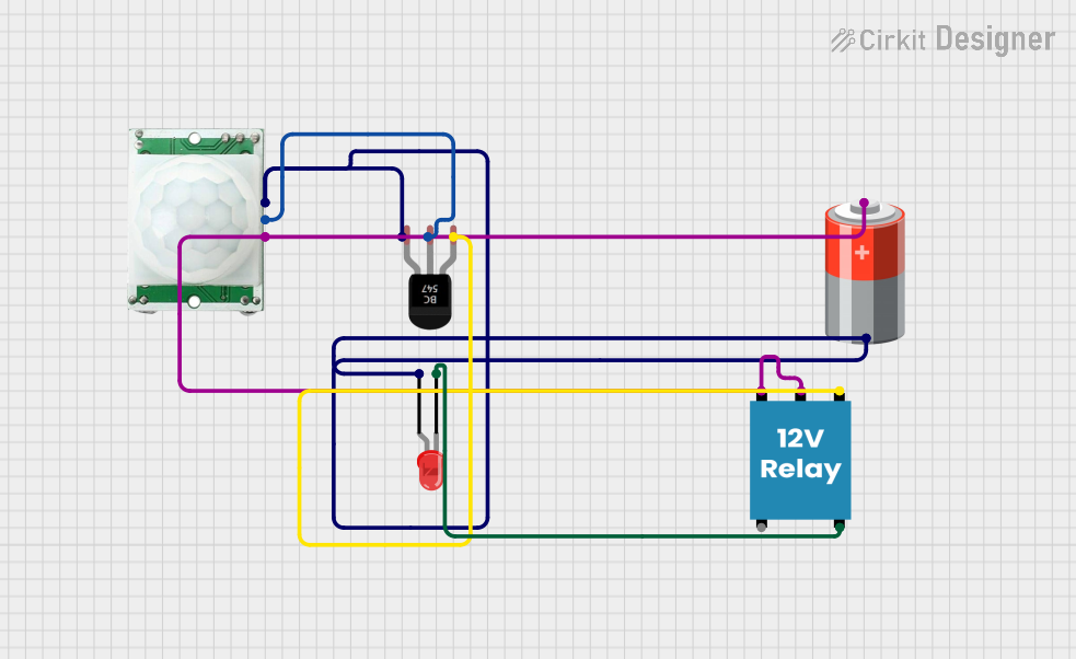
Circuit Documentation
Summary of the Circuit
This circuit appears to be designed to detect motion using a PIR (Passive Infrared) sensor and, upon detection, activate a relay which in turn powers an LED. The circuit is powered by a 5V battery. The PIR sensor output is connected to the base of a BC547 transistor, which acts as a switch. When the PIR sensor detects motion, it outputs a signal that turns on the transistor, allowing current to flow from the collector to the emitter. This current flow activates the relay, closing the circuit between the Common (C) and Normally Open (NO) contacts, which powers the LED.
Component List
PIR/Motion Sensor
- Description: A sensor that detects motion based on changes in infrared levels.
- Pins: GND, OUTPUT, VCC
5V Battery
- Description: A power source providing a 5V output.
- Pins: + (positive), - (negative)
12V Relay
- Description: An electromechanical switch that allows a low-power circuit to control a higher-power circuit.
- Pins: + (coil positive), - (coil negative), C (common), NC (normally closed), NO (normally open)
BC547 Transistor
- Description: A general-purpose NPN bipolar junction transistor used for switching and amplification.
- Pins: Collector, Base, Emitter
LED: Two Pin (red)
- Description: A red light-emitting diode used as an indicator.
- Pins: cathode (-), anode (+)
Wiring Details
PIR/Motion Sensor
- GND: Connected to the negative terminal of the 5V battery.
- OUTPUT: Connected to the base of the BC547 transistor.
- VCC: Connected to the positive terminal of the 5V battery.
5V Battery
- + (positive): Connected to the VCC of the PIR/Motion Sensor and the + pin of the 12V Relay.
- - (negative): Connected to the GND of the PIR/Motion Sensor, the emitter of the BC547 transistor, and the anode of the LED.
12V Relay
- + (coil positive): Connected to the positive terminal of the 5V battery.
- - (coil negative): Connected to the collector of the BC547 transistor.
- C (common): Connected to the positive terminal of the 5V battery.
- NO (normally open): Connected to the cathode of the LED.
BC547 Transistor
- Collector: Connected to the - (coil negative) of the 12V Relay.
- Base: Connected to the OUTPUT of the PIR/Motion Sensor.
- Emitter: Connected to the negative terminal of the 5V battery and the anode of the LED.
LED: Two Pin (red)
- cathode (-): Connected to the NO (normally open) contact of the 12V Relay.
- anode (+): Connected to the negative terminal of the 5V battery.
Documented Code
There is no embedded code provided for this circuit as there are no microcontroller components listed. The circuit functions purely on the basis of hardware components and their interconnections.