ESP8266 and Arduino UNO Based Robotic Controller with Ultrasonic Sensing and GSM Communication
Circuit Documentation
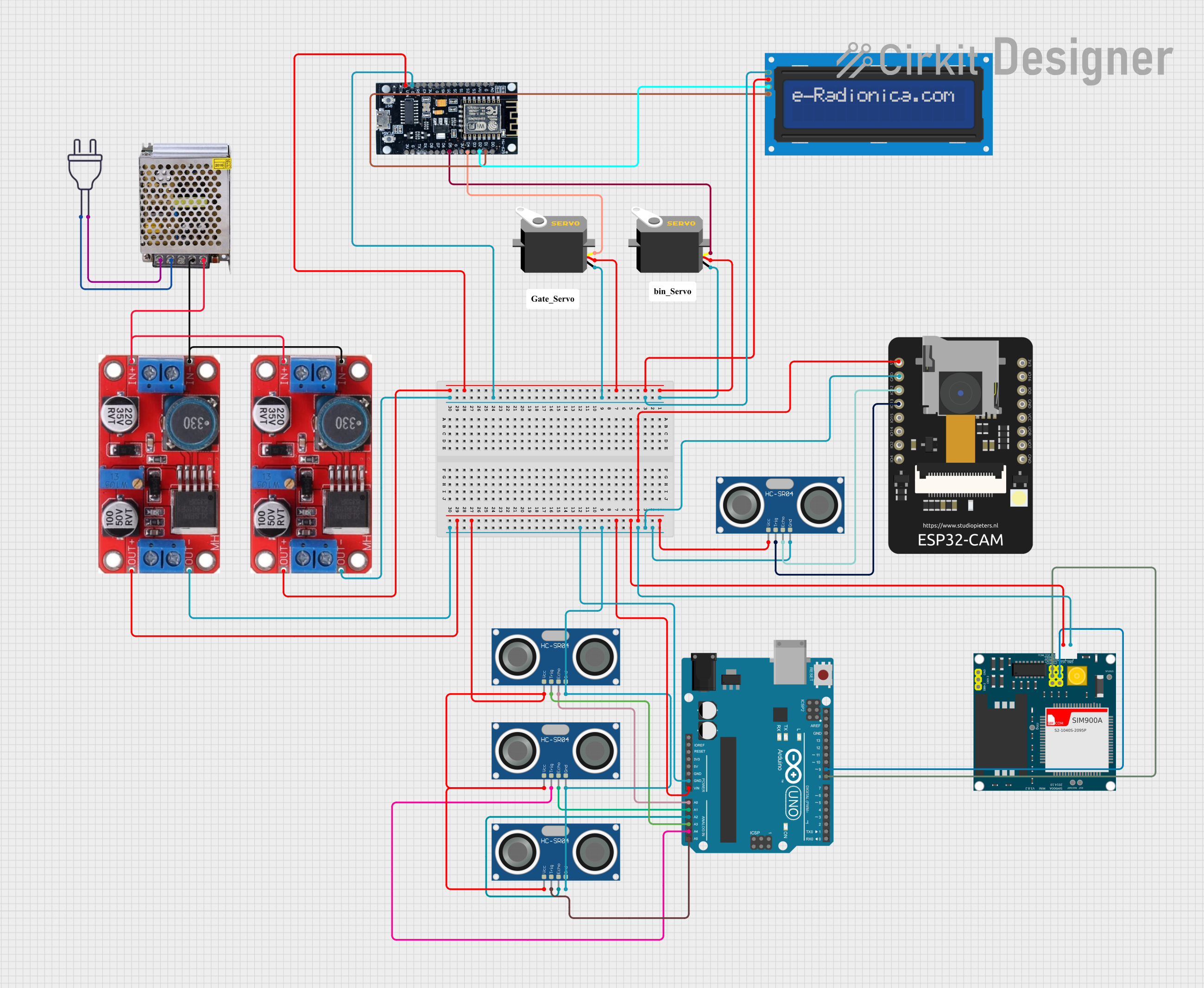
Summary
This circuit integrates a variety of components including microcontrollers, sensors, power supply units, a servo motor, an LCD screen, and a communication module. The primary microcontroller is an Arduino UNO, which interfaces with multiple HC-SR04 ultrasonic sensors and controls a SIM900A communication module. An ESP8266 Wi-Fi module is used for wireless connectivity and controls two servo motors. The ESP8266 also interfaces with an LCD screen via I2C communication. Power regulation is achieved using two XL6015 buck converters, which step down the voltage from a 12V 5A power supply. The ESP32 CAM module is included for camera functionalities.
Component List
Microcontrollers
- Arduino UNO: A microcontroller board based on the ATmega328P, commonly used for building digital devices and interactive objects that can sense and control objects in the physical world.
- ESP8266: A low-cost Wi-Fi microchip with full TCP/IP stack and microcontroller capability, used for wireless data communication.
Sensors
- HC-SR04 Ultrasonic Sensor: An ultrasonic distance sensor that provides 2cm to 400cm non-contact measurement functionality with a ranging accuracy that can reach up to 3mm.
- ESP32 CAM: A small camera module with Wi-Fi and Bluetooth capabilities, suitable for applications like surveillance cameras and face recognition.
Actuators
- Servo: An actuator that can rotate to a specified position, commonly used for precise control of angular motion.
Communication Modules
- SIM900A: A complete Dual-band GSM/GPRS module that can provide SMS and voice communication capabilities to embedded systems.
Power Supply and Conversion
- XL6015 Buck Converter: A DC-DC converter that steps down voltage while allowing for a high current output.
- POWER SUPPLY 12V 5AMP: A power supply unit that converts 220V AC to 12V DC, capable of delivering up to 5A of current.
- power 220v: Represents the main AC power source.
Display
- LCD screen 16x2 I2C: A liquid crystal display capable of showing 16 characters per line, with 2 lines. It uses the I2C communication protocol for interfacing.
Wiring Details
Microcontrollers
Arduino UNO
Vinconnected to the 5V output of the XL6015 Buck Converter.GNDconnected to the ground of the circuit.A0-A5connected to theECHOandTRIGpins of the HC-SR04 Ultrasonic Sensors.D8-D9connected to the5VTand5VRpins of the SIM900A module.
ESP8266
VINconnected to the 5V output of the XL6015 Buck Converter.Gconnected to the ground of the circuit.D1-D5connected to theSCLandSDApins of the LCD screen andpulsepins of the Servos.
Sensors
HC-SR04 Ultrasonic Sensors
VCCconnected to the 5V output of the XL6015 Buck Converter.GNDconnected to the ground of the circuit.ECHOandTRIGconnected to the corresponding analog pins on the Arduino UNO.
ESP32 CAM
5Vconnected to the 5V output of the XL6015 Buck Converter.GNDconnected to the ground of the circuit.GPIO12andGPIO13connected to theECHOandTRIGpins of an HC-SR04 Ultrasonic Sensor.
Actuators
- Servos
vccconnected to the 5V output of the XL6015 Buck Converter.gndconnected to the ground of the circuit.pulseconnected to theD4andD5pins of the ESP8266.
Communication Modules
- SIM900A
5Vconnected to the 5V output of the XL6015 Buck Converter.GNDconnected to the ground of the circuit.5VRand5VTconnected to theD9andD8pins of the Arduino UNO.
Power Supply and Conversion
XL6015 Buck Converters
INPUT +connected to the12V-24V Output (DC)of the POWER SUPPLY 12V 5AMP.INPUT -connected to theGND (DC)of the POWER SUPPLY 12V 5AMP.OUTPUT +andOUTPUT -provide 5V and GND to various components in the circuit.
POWER SUPPLY 12V 5AMP
220V Positive Pole (AC)connected to theneutral wireof the power 220v.220V Negative Pole (AC)connected to thehot wireof the power 220v.GND (DC)and12V-24V Output (DC)provide power to the XL6015 Buck Converters.
Display
- LCD screen 16x2 I2C
VCCconnected to the 5V output of the XL6015 Buck Converter.GNDconnected to the ground of the circuit.SCLandSDAconnected to theD1andD2pins of the ESP8266.
Documented Code
Arduino UNO Code (Instance ID: 9635889f-b0f7-4614-a523-b98247dcb2e4)
void setup() {
  // put your setup code here, to run once:

}

void loop() {
  // put your main code here, to run repeatedly:

}
Note: The provided code for the Arduino UNO is a template with empty setup and loop functions. This code needs to be populated with instructions to control the HC-SR04 sensors and communicate with the SIM900A module.
ESP8266 Code
No code was provided for the ESP8266. It is assumed that the ESP8266 will be programmed to control the servo motors and interface with the LCD screen via I2C.
End of Documentation