
Circuit Documentation
Summary
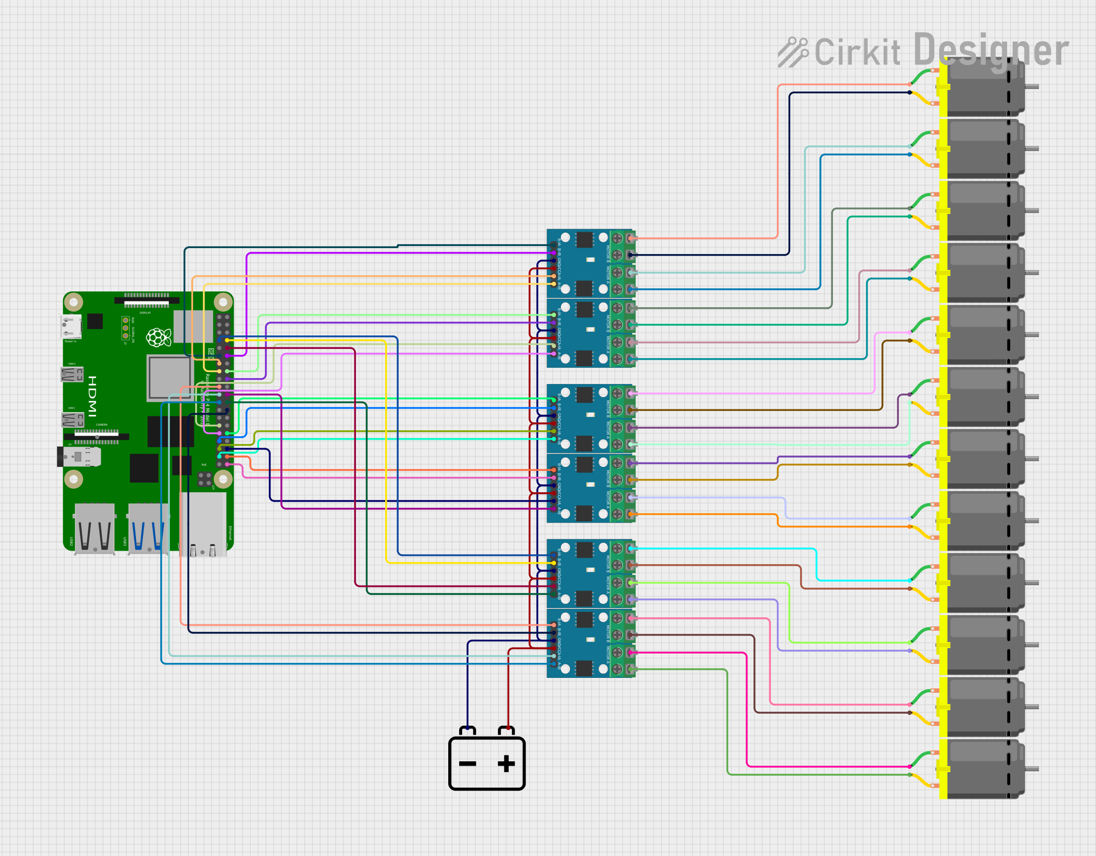
This circuit is designed to control multiple DC motors using a Raspberry Pi 4B as the main controller and several L9110 motor driver ICs. The Raspberry Pi 4B interfaces with the L9110 drivers to control the speed and direction of the connected DC motors. The motors are powered by a 12v Battery, which also supplies power to the L9110 drivers. The ground of the battery is shared across all L9110 drivers, creating a common ground for the system.
Component List
Raspberry Pi 4B
- Description: A single-board computer with GPIO pins used for controlling the L9110 motor drivers.
- Pins: 3V3, 5V, multiple GPIOs, GND, and others for various functions.
L9110 Motor Driver IC
- Description: A dual-channel motor driver capable of driving a pair of DC motors.
- Pins: MOTOR B-A, MOTOR B-B, MOTOR A-A, MOTOR A-B, B-IA, B-IB, GND, VCC, A-IA, A-IB.
DC Motor
- Description: A standard DC motor used for various mechanical actions.
- Pins: pin 1, pin 2.
12v Battery
- Description: Provides power to the motor drivers and motors.
- Pins: -, +.
Wiring Details
Raspberry Pi 4B
- GPIO4, GPIO14, GPIO15, GPIO17, GPIO18, GPIO27, GPIO22, GPIO23, GPIO24, GPIO10, GPIO9, GPIO25, GPIO11, GPIO8, GPIO7, GPIO5, GPIO6, GPIO12, GPIO13, GPIO19, GPIO16, GPIO26, GPIO20, GPIO21: Connected to various L9110 motor driver inputs for motor control signals.
- GND: Connected to the common ground network.
L9110 Motor Driver IC
- B-IA, B-IB, A-IA, A-IB: Control inputs connected to Raspberry Pi GPIO pins for motor control.
- MOTOR B-A, MOTOR B-B, MOTOR A-A, MOTOR A-B: Outputs connected to DC motor pins.
- GND: Connected to the common ground network.
- VCC: Connected to the positive terminal of the 12v Battery.
DC Motor
- pin 1, pin 2: Connected to the outputs of the L9110 motor driver ICs.
12v Battery
- -: Connected to the common ground network.
- +: Connected to the VCC input of all L9110 motor driver ICs.
Documented Code
No code has been provided for the microcontrollers in the circuit. The Raspberry Pi 4B would typically be programmed to control the L9110 motor driver ICs using its GPIO pins. The code would set the GPIO pins to high or low to control the direction and speed of the connected DC motors. Since no code is available, this section cannot be documented further.