
Arduino UNO Based Ultrasonic Distance Measurement with OLED Display and Alert System
View and Edit Project In Cirkit Designer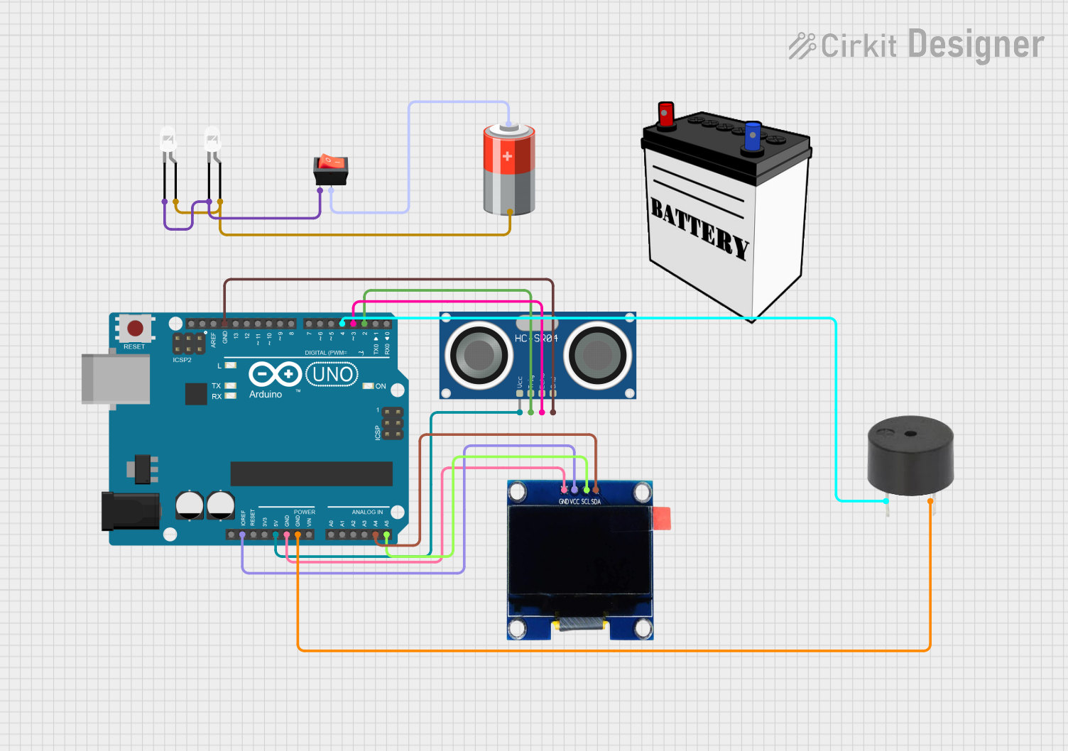
Circuit Documentation
Summary
This circuit integrates an Arduino UNO microcontroller with a variety of peripherals including an HC-SR04 Ultrasonic Sensor, an OLED 1.3" display, a buzzer, two white LEDs, and a rocker switch. The circuit is powered by a 5V battery and also includes a 12V battery for additional power requirements. The Arduino UNO serves as the central processing unit, interfacing with the ultrasonic sensor for distance measurement, the OLED display for data output, and the buzzer for audio signaling. The LEDs are controlled by a rocker switch and powered by the 5V battery.
Component List
Arduino UNO: A microcontroller board based on the ATmega328P. It has 14 digital input/output pins, 6 analog inputs, a 16 MHz quartz crystal, a USB connection, a power jack, an ICSP header, and a reset button.
HC-SR04 Ultrasonic Sensor: An ultrasonic distance sensor that provides 2cm to 400cm of non-contact measurement functionality with a ranging accuracy that can reach up to 3mm.
OLED 1.3" Display: A small display with an I2C interface for displaying data such as sensor readings or status information.
Buzzer: An electronic buzzer that can be used to generate tones or alerts.
12V Battery: A power source used to provide electrical energy to the circuit.
LED: Two Pin (white): A basic white LED used for indication or lighting purposes.
Rocker Switch: A switch that can be used to control the power to the LEDs.
5V Battery: A power source used to provide 5V to the circuit.
Wiring Details
Arduino UNO
- IOREF connected to OLED 1.3" VCC
- 5V connected to HC-SR04 Ultrasonic Sensor VCC
- GND connected to OLED 1.3" GND, buzzer GND, and HC-SR04 Ultrasonic Sensor GND
- A4 (SDA) connected to OLED 1.3" SDA
- A5 (SCL) connected to OLED 1.3" SCL
- D4 connected to buzzer PIN
- D3 connected to HC-SR04 Ultrasonic Sensor ECHO
- D2 connected to HC-SR04 Ultrasonic Sensor TRIG
HC-SR04 Ultrasonic Sensor
- VCC connected to Arduino UNO 5V
- TRIG connected to Arduino UNO D2
- ECHO connected to Arduino UNO D3
- GND connected to Arduino UNO GND
OLED 1.3" Display
- GND connected to Arduino UNO GND
- VCC connected to Arduino UNO IOREF
- SCL connected to Arduino UNO A5
- SDA connected to Arduino UNO A4
Buzzer
- PIN connected to Arduino UNO D4
- GND connected to Arduino UNO GND
LED: Two Pin (white)
- Cathode of both LEDs connected to rocker switch input
- Anode of both LEDs connected to 5V Battery negative terminal (-)
Rocker Switch
- Input connected to cathodes of both white LEDs
- Output connected to 5V Battery positive terminal (+)
5V Battery
- Positive terminal (+) connected to rocker switch output
- Negative terminal (-) connected to anodes of both white LEDs
12V Battery
- Not directly connected in the provided net list.
Documented Code
Arduino UNO Code (sketch.ino)
void setup() {
  // put your setup code here, to run once:

}

void loop() {
  // put your main code here, to run repeatedly:

}
The provided code is a template with empty setup() and loop() functions, which are the standard structure for Arduino sketches. The setup() function is intended to contain initialization code that runs once when the microcontroller is powered on or reset. The loop() function is for code that runs continuously as long as the Arduino is powered.
Additional Notes
- The code for the Arduino UNO is currently a placeholder and needs to be populated with the logic to interface with the HC-SR04 Ultrasonic Sensor, OLED display, and buzzer.
- The 12V Battery's role in the circuit is not defined in the net list, and it is not connected to any components in the provided information.
- The purpose of each part in the circuit has not been specified and should be detailed for a complete understanding of the circuit's functionality.