Arduino UNO-Based Environmental Monitoring and Motion Detection System
Circuit Documentation
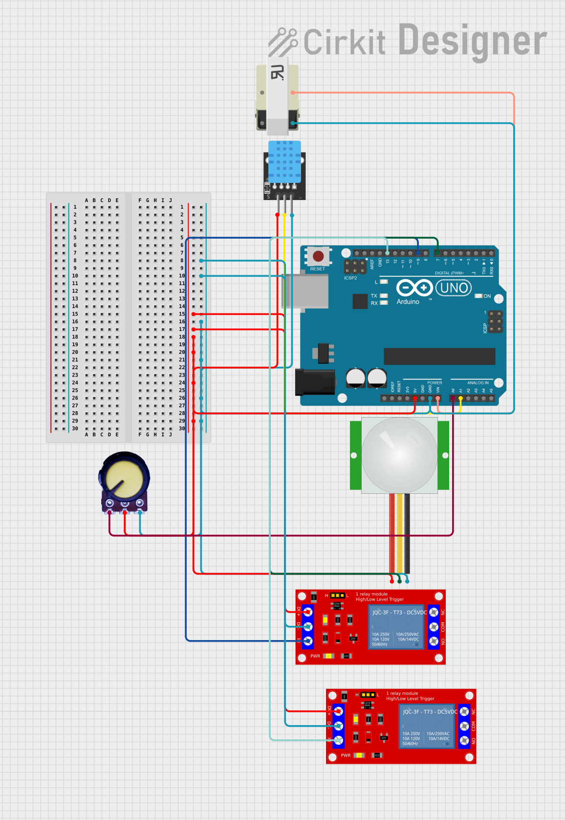
Summary
This document provides a detailed overview of a circuit that includes an Arduino UNO as the central microcontroller, interfaced with various sensors and modules including a DHT11 temperature and humidity sensor, a PIR motion sensor, two 1 Channel 5V Relay Modules, a potentiometer, and a transformer. The circuit is designed to monitor environmental conditions and detect motion, with the capability to control external devices through the relay modules. The Arduino UNO is powered through its Vin pin connected to the transformer, and it controls the relay modules and reads sensor data from the DHT11 and PIR sensor. The potentiometer is used to provide analog input to the Arduino.
Component List
- Arduino UNO: A microcontroller board based on the ATmega328P, featuring digital and analog I/O pins.
- 1 Channel 5V Relay Module: A module that allows for controlling high power devices using low voltage signals.
- DHT11: A sensor that measures temperature and humidity.
- PIR Sensor: A motion sensor that detects the presence of humans or animals.
- Potentiometer: A variable resistor that provides an adjustable voltage output.
- Transformer: A component that steps down or steps up voltage levels.
Wiring Details
Arduino UNO
- GND: Connected to the ground pins of both relay modules, the transformer, the potentiometer, the DHT11, and the PIR sensor.
- 5V: Powers both relay modules, the DHT11, and the PIR sensor.
- Vin: Receives power from the transformer.
- A0: Receives analog input from the potentiometer.
- A1: Connected to the signal pin of the DHT11.
- D7: Connected to the signal pin of the PIR sensor.
- D9: Controls the IN pin of one relay module.
- D13: Controls the IN pin of the other relay module.
1 Channel 5V Relay Module
- VCC+: Powered by the 5V output from the Arduino UNO.
- VCC- (GND): Connected to the ground network.
- IN: One relay module is controlled by the D13 pin, and the other by the D9 pin of the Arduino UNO.
DHT11
- 5V: Powered by the 5V output from the Arduino UNO.
- S: Signal pin connected to the A1 pin of the Arduino UNO.
- GND: Connected to the ground network.
PIR Sensor
- VDD: Powered by the 5V output from the Arduino UNO.
- SIG: Signal pin connected to the D7 pin of the Arduino UNO.
- GND: Connected to the ground network.
Potentiometer
- VCC: Connected to the 5V output from the Arduino UNO.
- Output: Provides analog input to the A0 pin of the Arduino UNO.
- GND: Connected to the ground network.
Transformer
- Pin 3: Connected to the ground network.
- Pin 4: Provides power to the Vin pin of the Arduino UNO.
Documented Code
void setup() {
  // put your setup code here, to run once:

}

void loop() {
  // put your main code here, to run repeatedly:

}
The provided code is a template with empty setup() and loop() functions, which are the entry points for Arduino sketches. The setup() function is called once when the sketch starts and is used to initialize settings, while the loop() function runs repeatedly, allowing the microcontroller to perform operations based on the inputs from sensors and control outputs like the relay modules. The actual implementation details need to be filled in based on the specific requirements of the circuit's operation.