
Arduino Nano-Based Smart Motor Control with Ultrasonic Sensor and Relay Switches
View and Edit Project In Cirkit Designer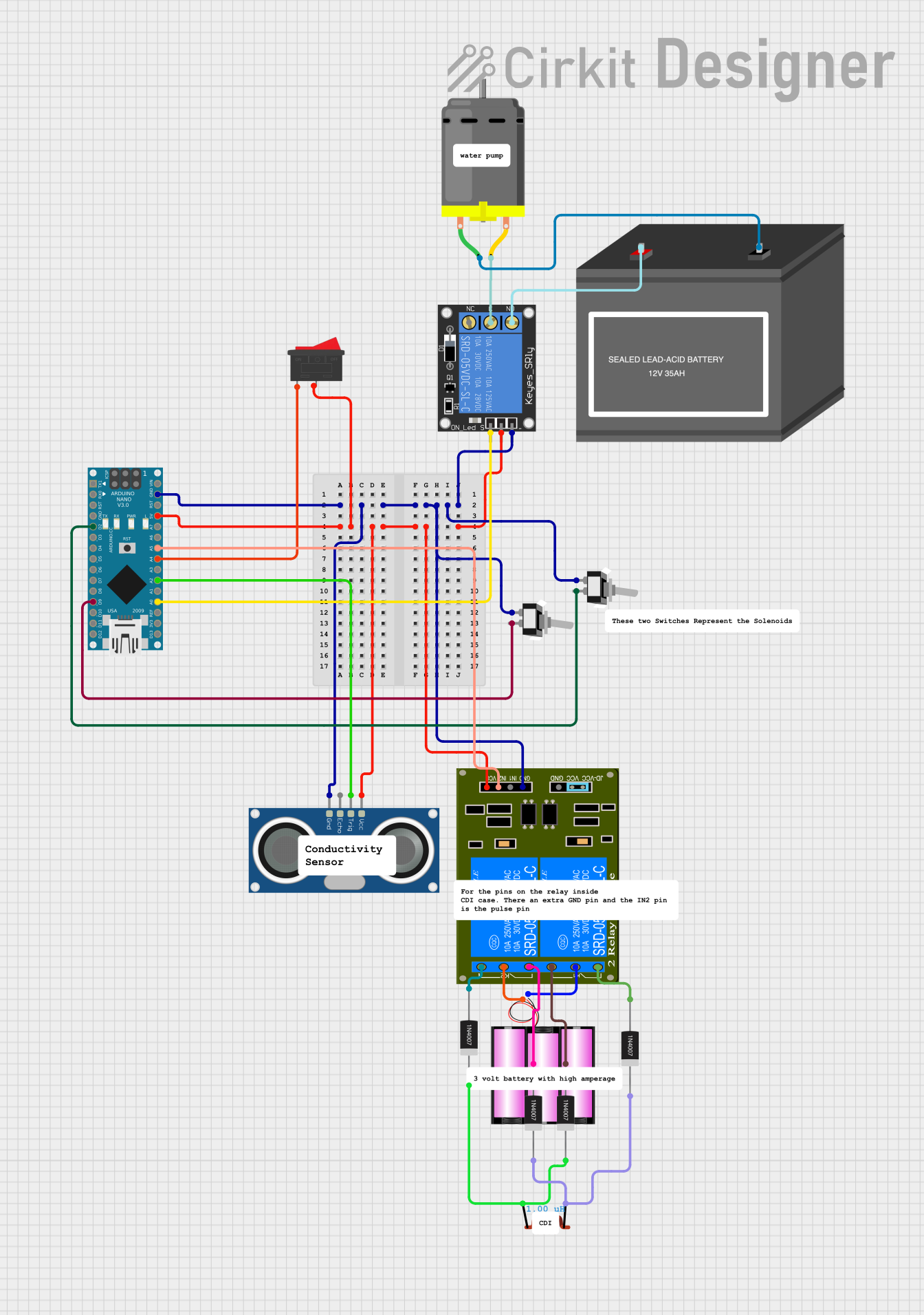
Circuit Documentation
Summary
This document provides a detailed overview of a circuit that includes an Arduino Nano microcontroller, various switches, relays, sensors, a DC motor, and power sources. The circuit is designed to control a DC motor and interact with an ultrasonic sensor, with the relays and switches providing control mechanisms.
Component List
Arduino Nano
- Description: A small, complete, and breadboard-friendly board based on the ATmega328P.
- Pins: D1/TX, D0/RX, RESET, GND, D2, D3, D4, D5, D6, D7, D8, D9, D10, D11/MOSI, D12/MISO, VIN, 5V, A7, A6, A5, A4, A3, A2, A1, A0, AREF, 3V3, D13/SCK
Rocker Switch
- Description: A switch that rocks back and forth to open or close a circuit.
- Pins: 1, 2
2-Channel Relay (5V 10A)
- Description: A relay module that can control two separate circuits.
- Pins: K1-Off, K1-In, K2-On, K2-In, K1-On, K2-Off, VCC, JD-GND, IN2, IN1, GND
1-Channel Relay (5V 10A)
- Description: A relay module that can control a single circuit.
- Pins: NC, signal, C, power, NO, ground
Toggle Switch SPST
- Description: A single-pole single-throw (SPST) toggle switch.
- Pins: L1, COM
HC-SR04 Ultrasonic Sensor
- Description: An ultrasonic sensor used for distance measurement.
- Pins: VCC, TRIG, ECHO, GND
DC Motor
- Description: A motor that runs on direct current (DC).
- Pins: pin 1, pin 2
12V Battery (mini)
- Description: A small 12V battery.
- Pins: -, +
Battery 12V
- Description: A 12V battery.
- Pins: +, -
1N4007 Rectifier Diode
- Description: A general-purpose silicon rectifier diode.
- Pins: Cathode, Anode
Inductor
- Description: An inductor with an inductance of 1 µH.
- Pins: pin 0, pin 1
Wiring Details
Arduino Nano
- D2 is connected to COM of the Toggle Switch SPST.
- D9 is connected to COM of another Toggle Switch SPST.
- GND is connected to:
- L1 of the Toggle Switch SPST.
- ground of the 1-Channel Relay (5V 10A).
- GND of the HC-SR04 Ultrasonic Sensor.
- GND of the 2-Channel Relay (5V 10A).
- 5V is connected to:
- power of the 1-Channel Relay (5V 10A).
- 2 of the Rocker Switch.
- VCC of the HC-SR04 Ultrasonic Sensor.
- VCC of the 2-Channel Relay (5V 10A).
- A5 is connected to IN2 of the 2-Channel Relay (5V 10A).
- A4 is connected to 1 of the Rocker Switch.
- A2 is connected to TRIG of the HC-SR04 Ultrasonic Sensor.
- A0 is connected to signal of the 1-Channel Relay (5V 10A).
Rocker Switch
- 1 is connected to A4 of the Arduino Nano.
- 2 is connected to 5V of the Arduino Nano.
2-Channel Relay (5V 10A)
- GND is connected to GND of the Arduino Nano.
- VCC is connected to 5V of the Arduino Nano.
- IN2 is connected to A5 of the Arduino Nano.
- K1-Off is connected to Anode of the 1N4007 Rectifier Diode.
- K1-In is connected to - of the Battery 12V.
- K2-On is connected to Anode of another 1N4007 Rectifier Diode.
- K2-In is connected to + of the Battery 12V.
- K1-On is connected to Anode of another 1N4007 Rectifier Diode.
- K2-Off is connected to Anode of another 1N4007 Rectifier Diode.
1-Channel Relay (5V 10A)
- ground is connected to GND of the Arduino Nano.
- power is connected to 5V of the Arduino Nano.
- signal is connected to A0 of the Arduino Nano.
- C is connected to pin 2 of the DC Motor.
- NO is connected to + of the 12V Battery (mini).
Toggle Switch SPST
- COM is connected to D2 of the Arduino Nano.
- L1 is connected to GND of the Arduino Nano.
HC-SR04 Ultrasonic Sensor
- VCC is connected to 5V of the Arduino Nano.
- TRIG is connected to A2 of the Arduino Nano.
- GND is connected to GND of the Arduino Nano.
DC Motor
- pin 1 is connected to - of the 12V Battery (mini).
- pin 2 is connected to C of the 1-Channel Relay (5V 10A).
12V Battery (mini)
- + is connected to NO of the 1-Channel Relay (5V 10A).
- - is connected to pin 1 of the DC Motor.
Battery 12V
- + is connected to K2-In of the 2-Channel Relay (5V 10A).
- - is connected to K1-In of the 2-Channel Relay (5V 10A).
1N4007 Rectifier Diode
- Anode of one diode is connected to K1-Off of the 2-Channel Relay (5V 10A).
- Anode of another diode is connected to K2-On of the 2-Channel Relay (5V 10A).
- Anode of another diode is connected to K1-On of the 2-Channel Relay (5V 10A).
- Anode of another diode is connected to K2-Off of the 2-Channel Relay (5V 10A).
- Cathode of one diode is connected to pin 0 of the Inductor.
- Cathode of another diode is connected to pin 1 of the Inductor.
- Cathode of another diode is connected to pin 0 of the Inductor.
- Cathode of another diode is connected to pin 1 of the Inductor.
Inductor
- pin 0 is connected to Cathode of one 1N4007 Rectifier Diode.
- pin 1 is connected to Cathode of another 1N4007 Rectifier Diode.
Documented Code
Arduino Nano Code
void setup() {
  // put your setup code here, to run once:

}

void loop() {
  // put your main code here, to run repeatedly:

}
This code is a basic template for the Arduino Nano. The setup function is where you initialize your settings, and the loop function is where the main code runs repeatedly. You can add your specific logic to control the relays, read the ultrasonic sensor, and manage the motor within these functions.