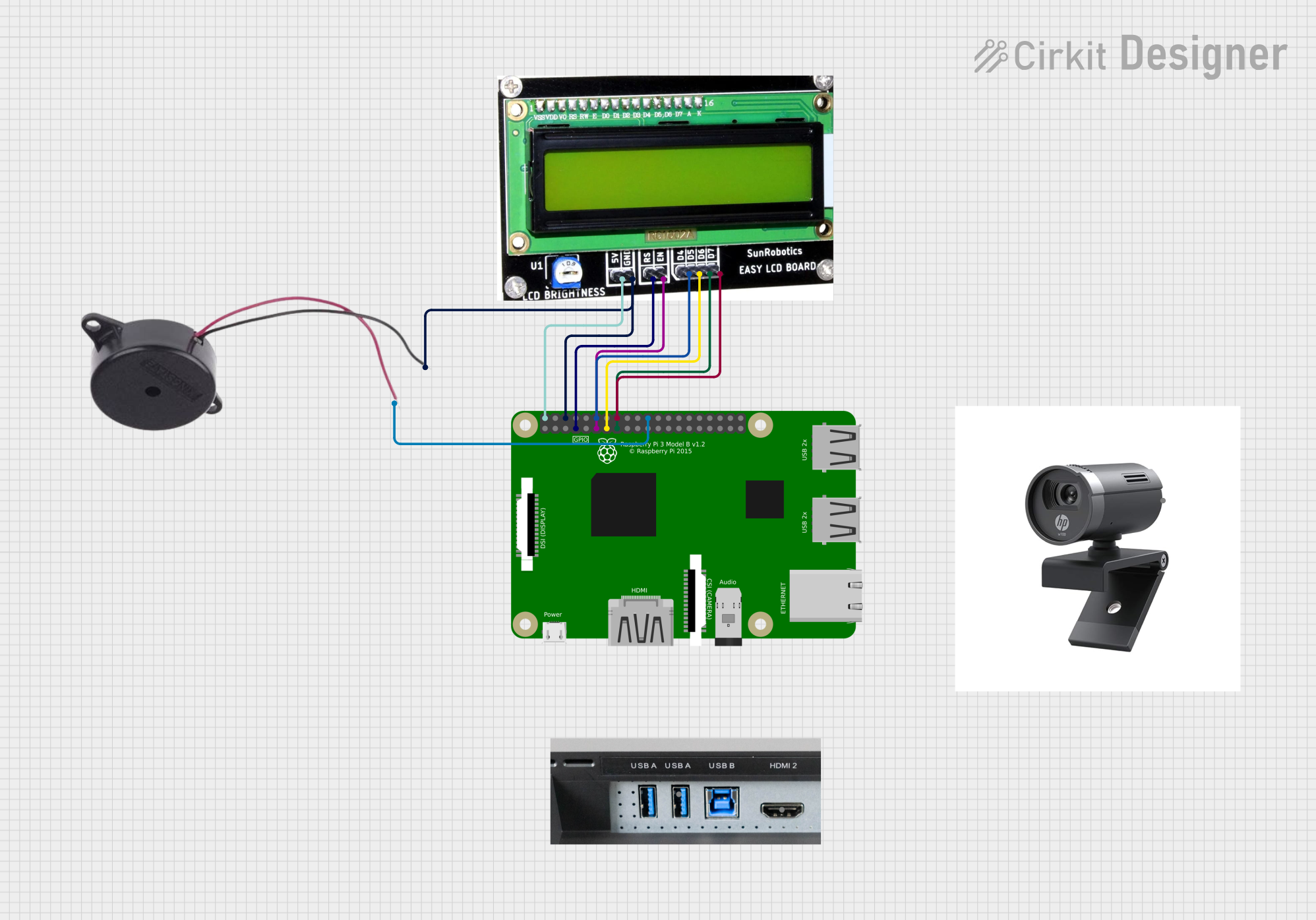
Raspberry Pi 3B Controlled LCD and Buzzer Interface

Circuit Documentation
Summary
The circuit in question is designed to interface a Raspberry Pi 3B with a 16x2 LCD module and a buzzer. The Raspberry Pi serves as the central processing unit, controlling the display output on the LCD and the activation of the buzzer. The LCD module is used for visual output, displaying text or numbers as required by the application. The buzzer provides audible feedback or alerts. Additionally, the circuit includes provisions for a monitor connection and a camera module, although these components are not directly wired in the provided net list.
Component List
Buzzer
- Description: An electromechanical component that emits sound when energized.
- Pins: POSITIVE, NEGATIVE
LCD Module 16x2
- Description: A liquid crystal display capable of showing 16 characters per line across 2 lines.
- Pins: D7, D6, D5, D4, EN, RS, GND, 5V
Raspberry Pi 3B
- Description: A small single-board computer with GPIO pins for interfacing with various electronic components.
- Pins: General Purpose Input/Output (GPIO) pins, Power pins (5V, GND), and others for various functions.
Monitor Connection
- Description: An interface for connecting a monitor, likely through HDMI or USB.
- Pins: HDMI, USB
Camera Module
- Description: A digital camera for capturing photos and videos.
- Pins: Input
Wiring Details
Buzzer
- POSITIVE: Connected to GPIO 22 of the Raspberry Pi 3B.
- NEGATIVE: Shared ground with Raspberry Pi 3B and LCD Module 16x2.
LCD Module 16x2
- D7: Connected to GPIO 16 of the Raspberry Pi 3B.
- D6: Connected to GPIO 15 of the Raspberry Pi 3B.
- D5: Connected to GPIO 13 of the Raspberry Pi 3B.
- D4: Connected to GPIO 12 of the Raspberry Pi 3B.
- EN: Connected to GPIO 11 of the Raspberry Pi 3B.
- RS: Connected to GPIO 7 of the Raspberry Pi 3B.
- GND: Shared ground with Raspberry Pi 3B and Buzzer.
- 5V: Connected to the 5V power pin of the Raspberry Pi 3B.
Raspberry Pi 3B
- GPIO 22: Connected to the POSITIVE pin of the Buzzer.
- GPIO 16: Connected to D7 of the LCD Module 16x2.
- GPIO 15: Connected to D6 of the LCD Module 16x2.
- GPIO 13: Connected to D5 of the LCD Module 16x2.
- GPIO 12: Connected to D4 of the LCD Module 16x2.
- GPIO 11: Connected to EN of the LCD Module 16x2.
- GPIO 7: Connected to RS of the LCD Module 16x2.
- GPIO 6: Connected to the NEGATIVE pin of the Buzzer (shared ground).
- 2(5V): Provides power to the 5V pin of the LCD Module 16x2.
Monitor Connection
- HDMI: (No wiring details provided)
- USB: (No wiring details provided)
Camera Module
- Input: (No wiring details provided)
Documented Code
No code has been provided for the microcontrollers in the circuit. If code becomes available, it should be documented here with explanations for each function and routine, as well as any relevant comments within the code to clarify its operation.