Cirkit Designer
Your all-in-one circuit design IDE
Home /
Project Documentation
Arduino UNO-Based Interactive LED and Buzzer System with OLED Display
Circuit Documentation
Summary
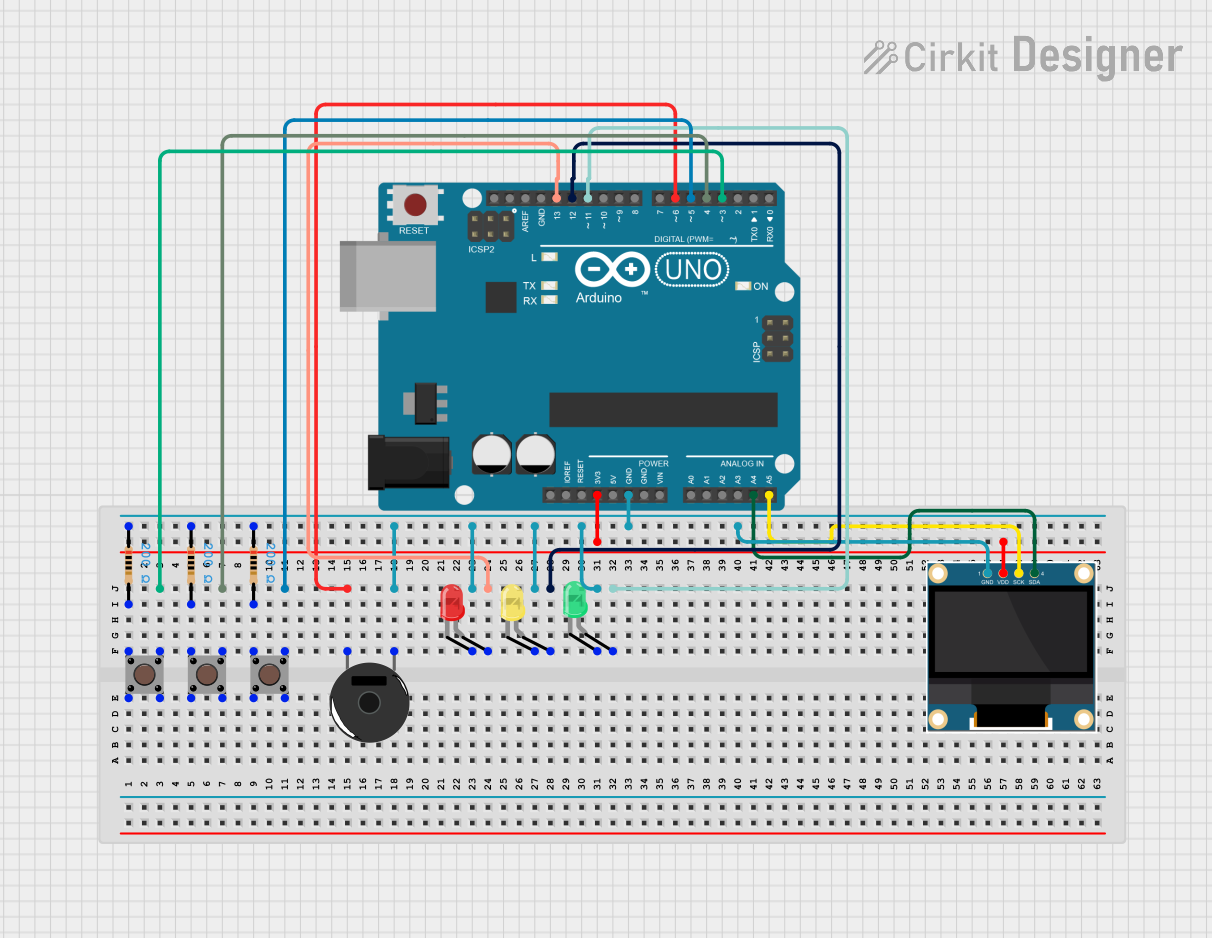
This circuit involves an Arduino UNO microcontroller interfacing with multiple components including pushbuttons, resistors, LEDs, a piezo buzzer, and an OLED display. The circuit is designed to demonstrate basic input and output operations using the Arduino platform.
Component List
Arduino UNO
- Description: A microcontroller board based on the ATmega328P.
- Pins: UNUSED, IOREF, Reset, 3.3V, 5V, GND, Vin, A0, A1, A2, A3, A4, A5, SCL, SDA, AREF, D13, D12, D11, D10, D9, D8, D7, D6, D5, D4, D3, D2, D1, D0
Resistor (200 Ohms)
- Description: A passive electrical component that implements electrical resistance.
- Pins: pin1, pin2
Pushbutton
- Description: A simple switch mechanism for controlling some aspect of a machine or a process.
- Pins: Pin 3 (out), Pin 4 (out), Pin 1 (in), Pin 2 (in)
Piezo Buzzer
- Description: An audio signaling device.
- Pins: pin 1, pin 2
LED: Two Pin (red)
- Description: A red light-emitting diode.
- Pins: cathode, anode
LED: Two Pin (green)
- Description: A green light-emitting diode.
- Pins: cathode, anode
LED: Two Pin (yellow)
- Description: A yellow light-emitting diode.
- Pins: cathode, anode
0.96" OLED
- Description: A small OLED display.
- Pins: GND, VDD, SCK, SDA
Wiring Details
Arduino UNO
- D3: Connected to Pin 3 (out) of Pushbutton
- D4: Connected to Pin 3 (out) of Pushbutton
- D5: Connected to Pin 3 (out) of Pushbutton
- D6: Connected to pin 2 of Piezo Buzzer
- D13: Connected to anode of LED: Two Pin (red)
- D12: Connected to anode of LED: Two Pin (yellow)
- D11: Connected to anode of LED: Two Pin (green)
- 3.3V: Connected to VDD of 0.96" OLED
- A4: Connected to SDA of 0.96" OLED
- A5: Connected to SCK of 0.96" OLED
- GND: Connected to pin1 of Resistor, pin1 of Resistor, pin1 of Resistor, cathode of LED: Two Pin (red), cathode of LED: Two Pin (yellow), cathode of LED: Two Pin (green), GND of 0.96" OLED
Resistor (200 Ohms)
- pin1: Connected to pin 1 of Piezo Buzzer, GND of Arduino UNO
- pin2: Connected to Pin 1 (in) of Pushbutton
Pushbutton
- Pin 3 (out): Connected to D3 of Arduino UNO
- Pin 1 (in): Connected to pin2 of Resistor
Piezo Buzzer
- pin 2: Connected to D6 of Arduino UNO
- pin 1: Connected to pin1 of Resistor
LED: Two Pin (red)
- anode: Connected to D13 of Arduino UNO
- cathode: Connected to GND of Arduino UNO
LED: Two Pin (green)
- anode: Connected to D11 of Arduino UNO
- cathode: Connected to GND of Arduino UNO
LED: Two Pin (yellow)
- anode: Connected to D12 of Arduino UNO
- cathode: Connected to GND of Arduino UNO
0.96" OLED
- GND: Connected to GND of Arduino UNO
- VDD: Connected to 3.3V of Arduino UNO
- SCK: Connected to A5 of Arduino UNO
- SDA: Connected to A4 of Arduino UNO
Code Documentation
Arduino UNO Code
void setup() {
  // put your setup code here, to run once:

}

void loop() {
  // put your main code here, to run repeatedly:

}
This code is a basic template for the Arduino UNO. The setup() function is where you initialize your components and settings, and the loop() function is where you place the main code that runs repeatedly.