Solar-Powered Battery Backup System with Automatic Transfer Switch and AC Outlet
Solar Power System Circuit Documentation
Summary
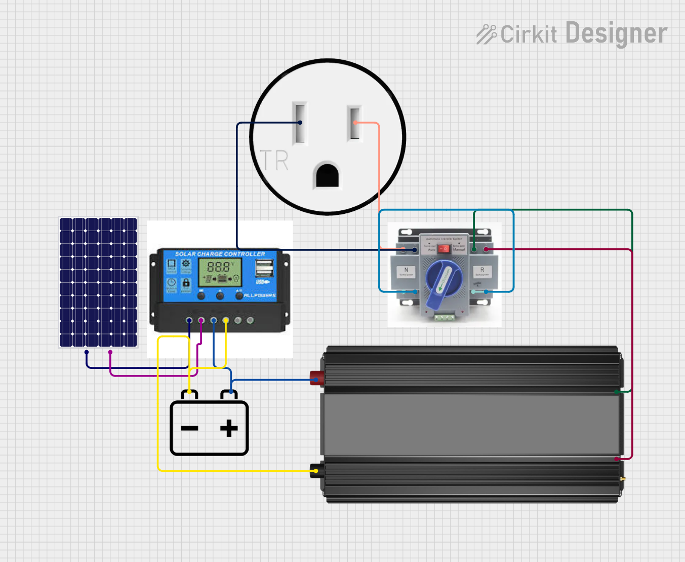
This document provides a detailed overview of a solar power system circuit designed to convert solar energy into usable electrical power for charging a 12V battery and supplying power to a 120V AC outlet. The system includes a solar panel, a charge controller, a 12V battery, a power inverter, an Automatic Transfer Switch (ATS), and a 120V outlet. The circuit ensures that the solar panel charges the battery through the charge controller, which regulates the charging process to protect the battery from overcharging. The power inverter converts the DC power from the battery into AC power, which is then routed through the ATS to the 120V outlet for use with standard appliances.
Component List
Solar Panel
- Description: A photovoltaic module that converts sunlight into electrical energy.
- Pins: Positive (+), Negative (-)
Charge Controller
- Description: A device that regulates the voltage and current coming from the solar panels going to the battery.
- Pins: Solar Positive, Solar Negative, Battery Positive, Battery Negative, Load Positive, Load Negative
12V Battery
- Description: A rechargeable battery that stores electrical energy for later use.
- Pins: Positive (+), Negative (-)
Power Inverter
- Description: An electronic device that converts low voltage DC power to standard 120V AC power.
- Pins: Positive (+), Negative (-)
ATS (Automatic Transfer Switch)
- Description: An electrical switch that switches a load between two sources, in this case, between grid power and inverter power.
- Pins: Positive (+), Negative (-)
120V Outlet
- Description: An electrical outlet that provides access to 120V AC power for standard appliances.
- Pins: AC Neutral, AC Hot
Wiring Details
Solar Panel
- Positive (+) connected to Charge Controller Solar Positive
- Negative (-) connected to Charge Controller Solar Negative
Charge Controller
- Solar Positive connected to Solar Panel Positive (+)
- Solar Negative connected to Solar Panel Negative (-)
- Battery Positive connected to 12V Battery Positive (+) and Power Inverter Positive (+)
- Battery Negative connected to 12V Battery Negative (-) and Power Inverter Negative (-)
- Load Positive (Not connected in the provided net list)
- Load Negative (Not connected in the provided net list)
12V Battery
- Positive (+) connected to Charge Controller Battery Positive and Power Inverter Positive (+)
- Negative (-) connected to Charge Controller Battery Negative and Power Inverter Negative (-)
Power Inverter
- Positive (+) connected to 12V Battery Positive (+), Charge Controller Battery Positive, and ATS Positive (+)
- Negative (-) connected to 12V Battery Negative (-), Charge Controller Battery Negative, and ATS Negative (-)
ATS (Automatic Transfer Switch)
- Positive (+) connected to Power Inverter Positive (+) and 120V Outlet AC Hot
- Negative (-) connected to Power Inverter Negative (-) and 120V Outlet AC Neutral
120V Outlet
- AC Neutral connected to ATS Negative (-)
- AC Hot connected to ATS Positive (+)
Documented Code
No microcontroller code was provided in the input. Therefore, this section is not applicable to the current documentation.
This documentation provides a comprehensive overview of the solar power system circuit, including the purpose and connection details of each component. The circuit is designed to be a standalone power system, capable of converting solar energy into electrical power for various applications.