Cirkit Designer
Your all-in-one circuit design IDE
Home /
Project Documentation
Wi-Fi Controlled System with ESP-8266 and Arduino UNO
Circuit Documentation
Summary
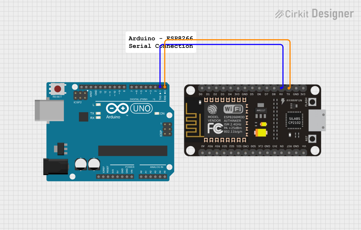
This document provides a detailed overview of a circuit involving an ESP-8266 Controller and an Arduino UNO. The ESP-8266 is connected to the Arduino UNO via its RX and TX pins. The document includes a component list, wiring details, and the code used in the microcontroller.
Component List
ESP-8266 Controller
- Description: A Wi-Fi microcontroller module used for IoT applications.
- Pins: A0, RSV, SD3, SD5, SD1, CMD, D0, D1, D2, D3, D4, 3V3, GND, D5, D6, SD0, CLK, RST, EN, D7, D8, RX, TX, Vin, 5V
- Purpose in Circuit: Provides Wi-Fi connectivity and acts as a microcontroller.
Arduino UNO
- Description: A microcontroller board based on the ATmega328P, commonly used for prototyping and educational purposes.
- Pins: UNUSED, IOREF, Reset, 3.3V, 5V, GND, Vin, A0, A1, A2, A3, A4, A5, SCL, SDA, AREF, D13, D12, D11, D10, D9, D8, D7, D6, D5, D4, D3, D2, D1, D0
- Purpose in Circuit: Acts as the main microcontroller for the circuit, interfacing with the ESP-8266.
Comment
- Description: A placeholder component for adding comments or notes in the circuit design.
- Pins: None
- Purpose in Circuit: Not used in this circuit.
Wiring Details
ESP-8266 Controller
- RX is connected to Arduino UNO D1
- TX is connected to Arduino UNO D0
Arduino UNO
- D1 is connected to ESP-8266 Controller RX
- D0 is connected to ESP-8266 Controller TX
Code Documentation
Arduino UNO Code
void setup() {
  // put your setup code here, to run once:

}

void loop() {
  // put your main code here, to run repeatedly:

}
Additional Documentation
This document provides a comprehensive overview of the circuit, including the components used, their connections, and the code running on the Arduino UNO.