
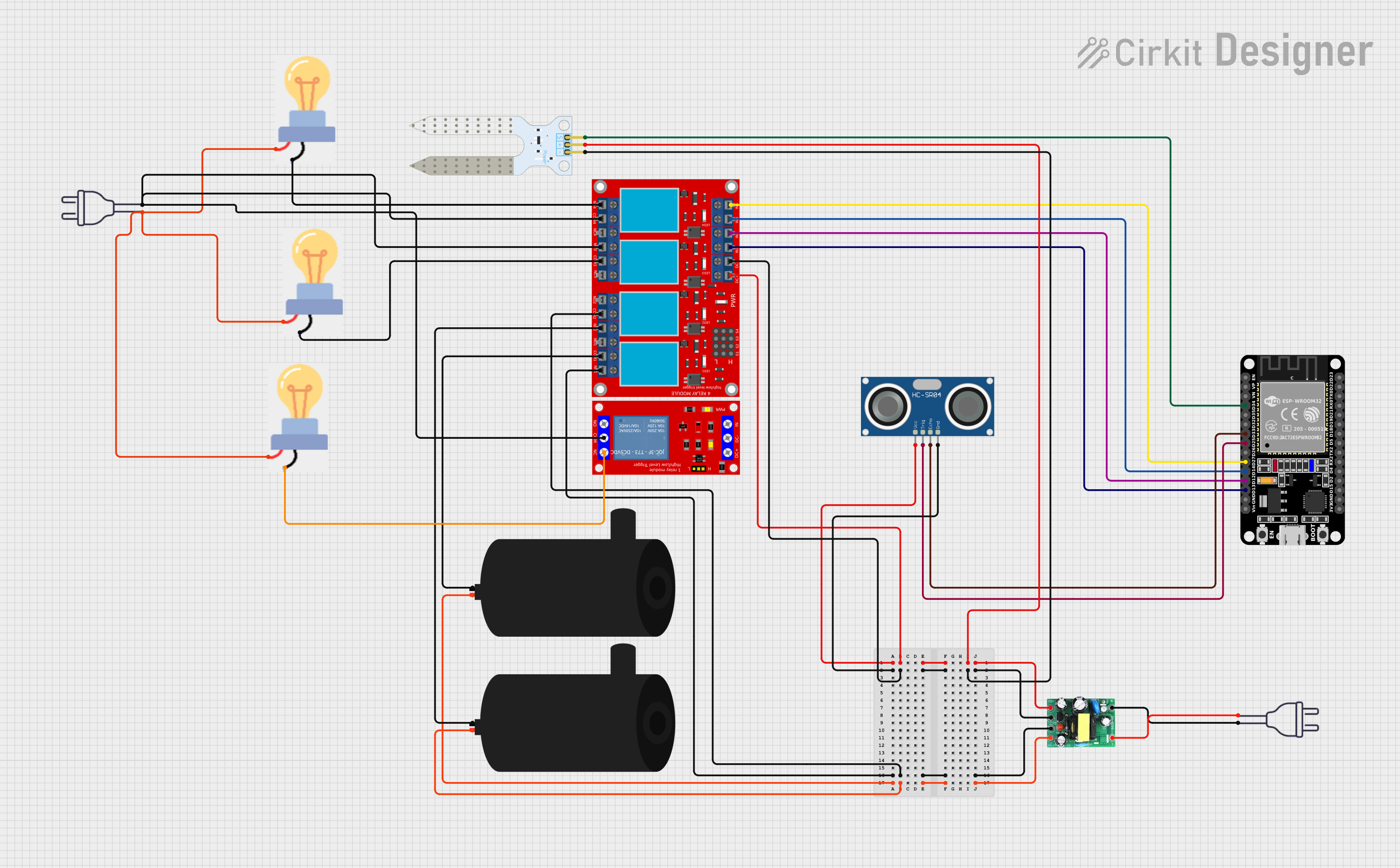
Circuit Documentation
Summary
This circuit is designed to interface an ESP32 microcontroller with various sensors and actuators, including an HC-SR04 ultrasonic sensor, a soil moisture sensor, a 4-channel relay module, two water pumps, an AC-to-DC converter (actodc), and multiple power sources including a 220V power supply. The ESP32 reads sensor data and controls the relays, which in turn manage the power to the water pumps and bulbs. The AC-to-DC converter supplies 5V to the low-voltage components, while the 220V power supply is used for the high-voltage components through the relay modules.
Component List
ESP32 (30 pin)
- Microcontroller with WiFi and Bluetooth capabilities.
- 30 GPIO pins including analog inputs, digital I/O, UART, I2C, and SPI.
HC-SR04 Ultrasonic Sensor
- Sensor for measuring distance via ultrasonic waves.
- Requires VCC, GND, TRIG, and ECHO connections.
Soil Moisture Sensor
- Sensor for detecting the moisture level in soil.
- Requires VCC, GND, and SIG connections.
4 Channel Relay Module
- Module with 4 relays to control high power devices.
- Each relay has Normally Open (N.O.), Common (COM), and Normally Closed (N.C.) terminals.
- Control pins (IN 1-4) for triggering each relay.
Water Pump
- Electric pump for moving water.
- Requires positive and negative connections.
AC-to-DC Converter (actodc)
- Power supply module that converts 220V AC to 12V and 5V DC outputs.
- Inputs for live and neutral wires, outputs for 12V, 5V, and ground.
Power 220V
- High voltage power supply.
- Provides hot and neutral wires for AC power.
1 Channel 5V Relay Module
- Single relay module for controlling one high power device.
- Has VCC, GND, IN, N.O., COM, and N.C. connections.
Bulb
- Electric light bulb.
- Requires power and GND connections.
Wiring Details
ESP32 (30 pin)
- D34 connected to Soil Moisture Sensor SIG
- D33 connected to HC-SR04 Ultrasonic Sensor ECHO
- D25 connected to HC-SR04 Ultrasonic Sensor TRIG
- D27, D14, D12, D13 connected to 4 Channel Relay Module IN 4, IN 3, IN 2, IN 1 respectively
HC-SR04 Ultrasonic Sensor
- VCC connected to 5V from actodc
- GND connected to GND from actodc
- TRIG connected to ESP32 D25
- ECHO connected to ESP32 D33
Soil Moisture Sensor
- VCC connected to 5V from actodc
- GND connected to GND from actodc
- SIG connected to ESP32 D34
4 Channel Relay Module
- VCC+ connected to 5V from actodc
- VCC- (GND) connected to GND from actodc
- IN 1, IN 2, IN 3, IN 4 connected to ESP32 D13, D12, D14, D27 respectively
- N.O. 4 connected to Bulb GND
- COM 4, N.O. 3 connected to 1 Channel 5V Relay Module COM and Power 220V neutral wire respectively
- COM 3 connected to Bulb GND
- N.C. 2 connected to Water Pump negative
- COM 1 connected to Water Pump negative
Water Pump
- Positive connected to 12V from actodc
- Negative connected to 4 Channel Relay Module N.C. 2 and COM 1
AC-to-DC Converter (actodc)
- 12v connected to Water Pump positive
- 5v connected to ESP32 Vin, HC-SR04 Ultrasonic Sensor VCC, Soil Moisture Sensor VCC, and 4 Channel Relay Module VCC+
-
- (GND) connected to ESP32 GND, HC-SR04 Ultrasonic Sensor GND, Soil Moisture Sensor GND, and 4 Channel Relay Module VCC- (GND)
- Live connected to Power 220V hot wire
- Neutral connected to Power 220V neutral wire
Power 220V
- Hot wire connected to actodc live
- Neutral wire connected to actodc neutral, 1 Channel 5V Relay Module COM, and Bulb power
1 Channel 5V Relay Module
- N.C. connected to Bulb GND
- COM connected to Power 220V neutral wire
Bulb
- GND connected to 4 Channel Relay Module N.O. 4, COM 3, and 1 Channel 5V Relay Module N.C.
- Power connected to Power 220V hot wire
Documented Code
No code was provided for the microcontrollers in the circuit. The documentation of the code would typically include descriptions of the functions, algorithms, and logic used to control the sensors and actuators based on the inputs and desired behavior. It would also include any libraries used, setup and loop functions, and any interrupt service routines or callbacks. Since no code is available, this section cannot be completed.