ESP32-Based Air Quality Monitoring System with Automated Exhaust Control

Circuit Documentation
Summary
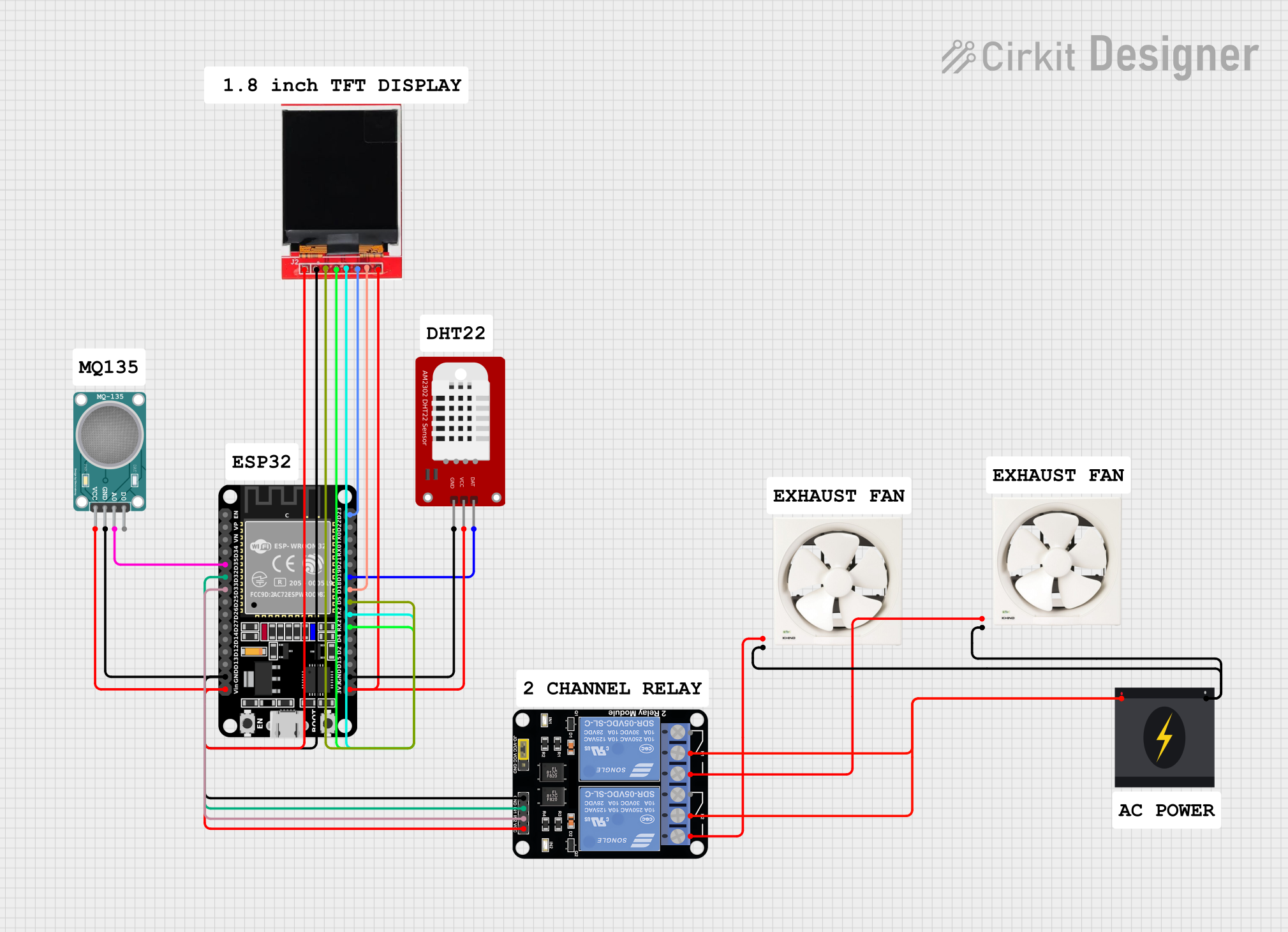
The circuit in question is designed to monitor air quality using an MQ-135 sensor and control two exhaust fans based on the sensor readings. The core of the circuit is an ESP32 microcontroller, which interfaces with the MQ-135 sensor, a DHT22 temperature and humidity sensor, and a TFT LCD display for output. The ESP32 also controls a 2-channel relay module that powers the exhaust fans. The circuit is powered by a 240V power source, with the ESP32 and other low-voltage components receiving regulated power from the source.
Component List
ESP32 (30 pin)
- Description: A microcontroller with Wi-Fi and Bluetooth capabilities.
- Pins: EN, VP, VN, D34, D35, D32, D33, D25, D26, D27, D14, D12, D13, GND, Vin, D23, D22, TX0, RX0, D21, D19, D18, D5, TX2, RX2, D4, D2, D15, 3V3
DHT22
- Description: A sensor for measuring temperature and humidity.
- Pins: GND, VCC, DAT
TFT LCD Display ST7735S
- Description: A small LCD display for visual output.
- Pins: Vcc, GND, CS, RESET, A0, SDA, SCK, LED
MQ-135 SENSOR AIR QUALITY
- Description: A sensor for detecting a wide range of gases, including NH3, NOx, alcohol, benzene, smoke, and CO2.
- Pins: VCC, GND, A0, D0
Relay Module 2 Channel
- Description: A module with two relays to control high power devices.
- Pins: GND, IN1, IN2, VCC, NC1, COM, NO1, NC2, NO2
Exhaust Fan 12"
- Description: A 12-inch exhaust fan for ventilation.
- Pins: Live, Neutral
240v Power Source
- Description: The main power source for the circuit.
- Pins: Live, Neutral
Wiring Details
ESP32 (30 pin)
- GND connected to common ground.
- Vin connected to VCC of Relay Module, MQ-135 Sensor, and TFT LCD Display.
- D35 connected to A0 of MQ-135 Sensor.
- D32 connected to IN1 of Relay Module.
- D33 connected to IN2 of Relay Module.
- D23 connected to SDA of TFT LCD Display.
- D19 connected to DAT of DHT22.
- D18 connected to SCK of TFT LCD Display.
- D5 connected to CS of TFT LCD Display.
- TX2 connected to A0 of TFT LCD Display.
- RX2 connected to RESET of TFT LCD Display.
- 3V3 connected to VCC of DHT22 and LED of TFT LCD Display.
DHT22
- GND connected to common ground.
- VCC connected to 3V3 of ESP32.
- DAT connected to D19 of ESP32.
TFT LCD Display ST7735S
- GND connected to common ground.
- Vcc connected to Vin of ESP32.
- CS connected to D5 of ESP32.
- RESET connected to RX2 of ESP32.
- A0 connected to TX2 of ESP32.
- SDA connected to D23 of ESP32.
- SCK connected to D18 of ESP32.
- LED connected to 3V3 of ESP32.
MQ-135 SENSOR AIR QUALITY
- GND connected to common ground.
- VCC connected to Vin of ESP32.
- A0 connected to D35 of ESP32.
Relay Module 2 Channel
- GND connected to common ground.
- IN1 connected to D32 of ESP32.
- IN2 connected to D33 of ESP32.
- VCC connected to Vin of ESP32.
- COM connected to Live of 240v Power Source.
- NO1 connected to Live of Exhaust Fan 12" (Instance 1).
- NO2 connected to Live of Exhaust Fan 12" (Instance 2).
Exhaust Fan 12" (Instance 1)
- Live connected to NO1 of Relay Module.
- Neutral connected to Neutral of 240v Power Source.
Exhaust Fan 12" (Instance 2)
- Live connected to NO2 of Relay Module.
- Neutral connected to Neutral of 240v Power Source.
240v Power Source
- Live connected to COM of Relay Module.
- Neutral connected to Neutral of both Exhaust Fans.
Documented Code
No code has been provided for the microcontrollers in the circuit. The documentation of the code would typically include a description of the functionality, setup, and main loop, along with any functions or libraries used. Since no code is available, this section cannot be completed.