
ESP32-Based Health Monitoring System with MAX30102 and MAX30205 Sensors
View and Edit Project In Cirkit Designer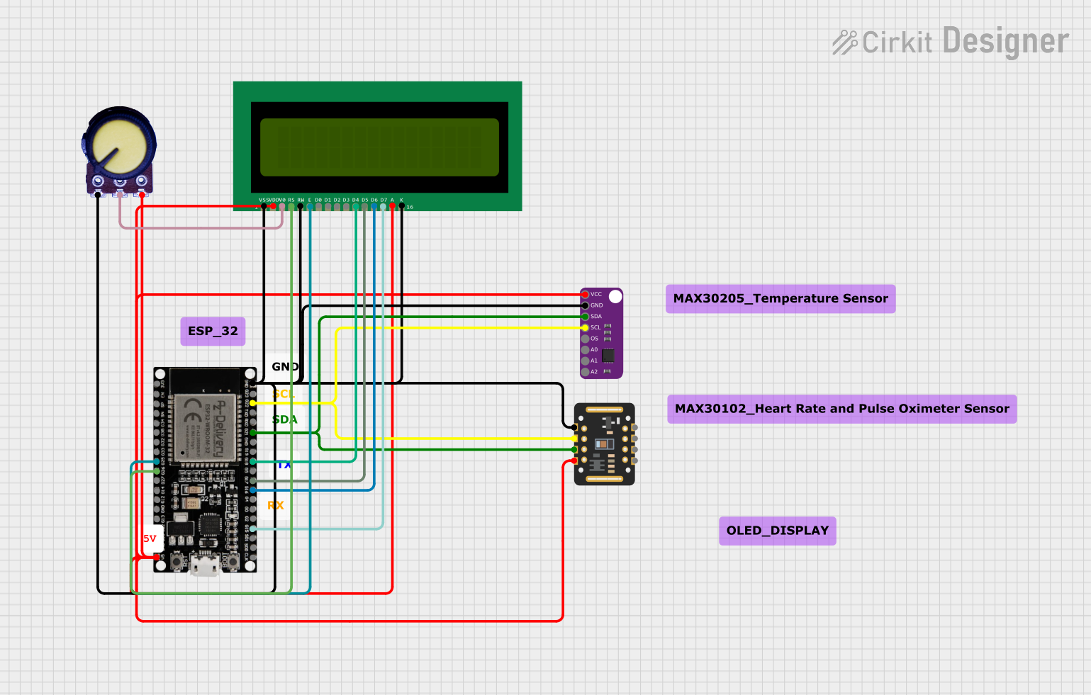
Circuit Documentation
Summary
This circuit is designed to monitor and display various health parameters such as temperature and heartbeat. It features an ESP32 microcontroller interfaced with a MAX30102 pulse oximeter and heart-rate sensor, a MAX30205 temperature sensor, and a 16x2 LCD display for output. The circuit also includes a potentiometer to adjust the contrast of the LCD. The ESP32 microcontroller is programmed to process the sensor data and manage the display interface, providing a user-friendly menu system to navigate through the health metrics.
Component List
ESP32 38 PINS
- Description: A microcontroller with Wi-Fi and Bluetooth capabilities, featuring a wide range of GPIO pins.
- Purpose: Acts as the central processing unit for the circuit, handling sensor data, controlling the LCD display, and managing user input.
MAX30102
- Description: An integrated pulse oximetry and heart-rate monitor sensor module.
- Purpose: Measures the oxygen saturation in the blood and the heart rate.
MAX30205
- Description: A human body temperature sensor.
- Purpose: Measures the temperature of the human body with high accuracy.
16X2 LCD
- Description: A liquid crystal display that can show 16 characters per line on 2 lines.
- Purpose: Displays the health parameters and menu options to the user.
Potentiometer
- Description: A three-terminal resistor with an adjustable voltage divider.
- Purpose: Adjusts the contrast of the LCD display.
Wiring Details
ESP32 38 PINS
- GND: Connected to the ground plane.
- G23: Not connected.
- G22: Connected to SCL pins of MAX30102 and MAX30205 for I2C communication.
- TXD: Not connected.
- RXD: Not connected.
- G21: Connected to SDA pins of MAX30102 and MAX30205 for I2C communication.
- G19 - G0: Not connected.
- G2: Not connected.
- G15: Connected to D7 pin of the 16X2 LCD.
- SDI, SD0, CLK: Not connected.
- 3V3: Not connected.
- EN: Not connected.
- SP, SN: Not connected.
- G34 - G27: Not connected.
- G14, G12, G13: Not connected.
- SD2, SD3: Not connected.
- 5V: Connected to VCC pins of MAX30102, MAX30205, and VDD pin of the 16X2 LCD.
MAX30102
- VIN: Connected to 5V from ESP32.
- SDA: Connected to G21 of ESP32.
- SCL: Connected to G22 of ESP32.
- GND: Connected to the ground plane.
- RD, IRD, INT: Not connected.
MAX30205
- VCC: Connected to 5V from ESP32.
- GND: Connected to the ground plane.
- SDA: Connected to G21 of ESP32.
- SCL: Connected to G22 of ESP32.
- OS, A0, A1, A2: Not connected.
16X2 LCD
- VSS, K, RW: Connected to the ground plane.
- VDD, A: Connected to 5V from ESP32.
- V0: Connected to the output of the potentiometer.
- RS: Connected to G26 of ESP32.
- E: Connected to G25 of ESP32.
- D4: Connected to G18 of ESP32.
- D5: Connected to G17 of ESP32.
- D6: Connected to G16 of ESP32.
- D7: Connected to G15 of ESP32.
- D0 - D3: Not connected.
Potentiometer
- GND: Connected to the ground plane.
- Output: Connected to V0 pin of the 16X2 LCD.
- VCC: Connected to 5V from ESP32.
Documented Code
The code for the ESP32 microcontroller is written in C++ and is designed to be compiled and uploaded using the Arduino IDE. The code includes libraries for the LCD display and EEPROM, defines a menu structure for navigating through the health metrics, and contains functions for managing the display, reading sensor data, and checking for abnormal readings.
// Include necessary libraries
#include <LiquidCrystal.h>
#include <EEPROM.h>

// Define the menu structure
typedef struct linker {
  // ... (omitted for brevity)
} Menu;

// Initialize the LCD with the appropriate pins
LiquidCrystal lcd(26, 25, 18, 17, 16, 15);

// Define global variables for health metrics and thresholds
// ... (omitted for brevity)

// Define functions for configuration and display
// ... (omitted for brevity)

void setup() {
  // Set up serial communication and LCD
  // Initialize menu structures and configure pins
  // ... (omitted for brevity)
}

void loop() {
  // Main program loop that checks for button presses
  // Updates health metrics and displays warnings if necessary
  // ... (omitted for brevity)
}
The full code includes detailed setup functions for each menu and sub-menu, functions to update and display the maximum and minimum recorded temperatures and heartbeats, and functions to handle user input from buttons connected to the ESP32. The code also simulates temperature and heartbeat readings for demonstration purposes.